


3. Pull lightly on the recoil grip until you feel significant resistance, then pull sharply.
Do not allow the recoil rope to 'snap' back into the recoil housing. Allow the recoil
to gently rewind into the recoil housing.
See your engine manual for instructions
specific to your unit.
If the engine does no start af er tu ning the engine over a few times, smell for fuel near the air cleaner.
If there is a significant gasoline smell coming from the air cleaner turn the choke lever
t
t
r
,
off and attempt to start the engine with the choke off.
4. After the engine has started, turn the engine's choke lever to the 'Off' position.
5.
Power is now present
. Connect or 'turn on' the loads you wish to operate.
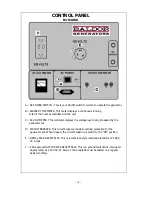
B.
Starting with electric start:
1.
If the generator's control panel has an engine 'On/Off' switch on it, turn it on at this
time.
2. Either push the engine's start switch or turn the key switch fully clockwise to engage
the electric start motor.
3. Do not allow the starter motor to crank for more than 10 seconds at a time.
4. Allow 20 seconds between starter motor cranking attempts.
5. Once the engine has started, release the starting switch and do not attempt to
reengage it.
If the engine does not start after turning the engine over a few times, smell for fuel near the
air cleaner. If there is a significant gasoline smell coming from the air cleaner, turn the choke
lever off and attempt to start the engine with the choke off.
6. After the engine has started, turn the engine's choke lever to the 'Off' position.
7.
Power is now present
. Connect or 'turn on' the loads you wish to operate.
STOPPING THE ENGINE:
1. Disconnect or 'Turn Off' all loads connected to the generator set.
2. Turn any engine 'On/Off' switches to the 'Off' position.
3. Push engine 'Stop' switch if so equipped.
4. Turn any engine key switches to the 'Off' position.
5. Turn all fuel valves off.
- 10 -
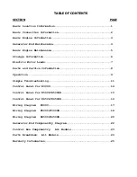
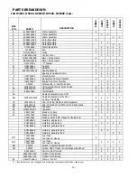
Summary of Contents for Premier 'K'
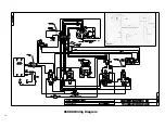
Page 24: ...K3000 Wiring Diagram 17...
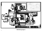
Page 25: ...K5000 Wiring Diagram 18...
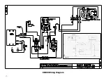
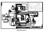
Page 26: ...K5000E Wiring Diagram 19...
Page 27: ...K6500 Wiring Diagram 20...
Page 28: ...K6500E Wiring Diagram 21...
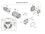
Page 29: ...Generator End Componentry 22...
Page 30: ...CONTROL BOX COMPONENTRY 23...


