Appendix A
Powerchief
R
Series
Powerchief
R
Series A-1
MN2412
Information in this Appendix applies to the following Baldor Generators:
PC30H, PC40H, PC50H, PC60H, PC90VE
Caution:
The brass connecting tab on some 120VAC duplex receptacles have been removed. Each
receptacle is powered by a separate generator winding. When replacing a receptacle, inspect
the brass tab that normally links both receptacles. If it is removed, be sure to remove the
brass tab from the replacement receptacle before it is installed. Failure to remove the tab will
cause a direct short to the generator windings and cause possible generator damage.
Operator Panel Configuration
Figure A-1 PC30H Operator Panel
Duplex Receptacle
.
Duplex receptacle is rated at 125VAC, 15 Amps.
Receptacle.
Single style receptacle rated for 125VAC, 15 Amps.
Circuit Breaker.
Provide overload protection for the generator set.
Press to Reset
Figure A-2 PC40H, PC50H, PC60H, PC90VE Operator Panel
NEMA 5−20R GFCI Receptacle
.
This ground fault circuit interrupter duplex receptacle is rated at 125VAC, 20 Amps.
NEMA L5−30R Receptacle.
Twist−lock style receptacle rated for 125VAC, 30 Amps.
NEMA L14−30R Receptacle.
Twist−lock style receptacle rated for 125/250VAC, 30 Amp
Circuit Breakers.
Provide overload protection for the generator set.
120 VOLTS
120 VOLTS
CIRCUIT BREAKERS
120/240 VOLTS
Press to Reset
Summary of Contents for PC Series
Page 1: ...PowerchiefR POW R Products Generator Series PC Installation Operating Manual 5 05 MN2412...
Page 4: ...ii Table of Contents MN2412...
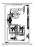
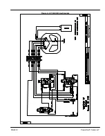
Page 26: ...A 4 PowerchiefR Series MN2412 Figure A 5 PC30H Wiring Diagram...
Page 27: ...PowerchiefR Series A 5 MN2412 Figure A 6 PC40H Wiring Diagram...
Page 28: ...A 6 PowerchiefR Series MN2412 Figure A 7 PC50H Wiring Diagram...
Page 29: ...PowerchiefR Series A 7 MN2412 Figure A 8 PC60H Wiring Diagram...
Page 30: ...A 8 PowerchiefR Series MN2412 Figure A 9 PC90VE Wiring Diagram...


