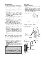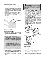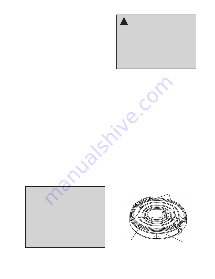
Hose Clamps
Keeper
(Safety Ring)
Power Spring
3. Retract the hose and remove necessary
wraps until
all power spring tension has been
removed
.
4. Remove lock nut (44) from shaft (5).
5. Pull out side panels and shaft assembly from
base collar (27).
6. Remove reel from clap and lay it on a flat work
surface so the base plate (25) of the reel is on
the bottom.
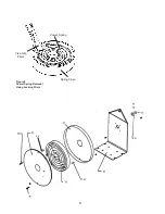
7. Remove nuts (13) and then remove spring case
assembly (20 & 23) with both screws (35 & 36)
and spacers (45 & 46) still attached.
8. Be sure case is laying flat on the work surface.
Then using extreme caution, remove both safety
cotter pins from sides of case and lift up on the
spring case cover (20) to expose the power
spring.
9.
Carefully Inspect the Power Spring
; If either end
of the power spring is worn or damaged and
will not engage the ratchet properly replace the
power spring.
If the power spring has become uncoiled inside
the spring case, the “keeper” has failed. (See
Figure 8) It is strongly advised that you replace
the complete spring case assembly. The “keeper”
is a metal band that is placed around the power
spring to keep it from uncoiling when removed
from the case. If you attempt to remove the
power spring when this condition has occurred
the spring
will uncoil quickly
and can
cause
serious bodily injury.
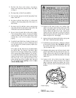
10. Removing the power spring; use locking type
pliers to compress and hold several rows of the
power spring together, then lift out the power
spring slowly and place two hose clamp style
clamps around the power spring and keeper
before disposing of power spring. (See Figure 8
below & Figure 9 on next page)
11. Apply a light coat of grease inside the spring case
and cover. Install new power spring.
12. Install the new power spring, making sure that it
is laid into the spring case
Clockwise
and that
the outside end loop is around spring case bolt
(35) and spacer (46).
13. Replace spring case cover (20) and insert cotter
pins through sides of spring case (23) and cover.
Tighten case and cover to reel base (25) and
insert side panel and shaft assembly into base
collar (27).
14. Tighten 1-3/8”-20 nut (44) onto shaft, inspect
complete reel for proper function and adjust
power spring as needed by adding one to two
loops of hose at a time to increase power spring
tension.
Figure 8
Keeper & Safety Clamps
!
Pressure Relief Procedure:
To reduce the risk of serious bodily injury,
including fluid injection or splashing into the eyes
and/or onto the skin, follow this procedure below
before maintaining and/or repairing the pump,
solenoid and/or impulse meter or any part of your
system.
1. Disconnect the air supply from the pump.
2. Open the dispensing valve into an approved
waste container to relieve pressure on the
system.
3. Leave any bleed-type drain valves open until
you are ready to use the system again.
7
W A R N I N G :
USE EXTREME
CAUTION WHEN HANDLING THE POWER
SPRING! The spring is
ALWAYS
under great
tension and could be propelled from the case
with enough force to cause
SERIOUS
bodily
injury. To reduce the risk of serious bodily
injury, use extreme caution when removing
the top cover (20). Be sure the spring case is
lying flat, and then carefully lift up the cover
to expose the power spring.


