CONCEPT P4 INSTRUCTION MANUAL
3
Amp
A
B
C
D
MADE IN FRANCE
100 - 240 V 50/60 Hz
TEST
10 A Slo. 220 V
20 A Slo. 110 V
A
CONCEPT P4
Auto
Auto Max
100%
ind
X
2
1
3
17
14
6
12
13
7
8
9
10
11
4
19
20
15
16
22
5
21
18
B
C
D
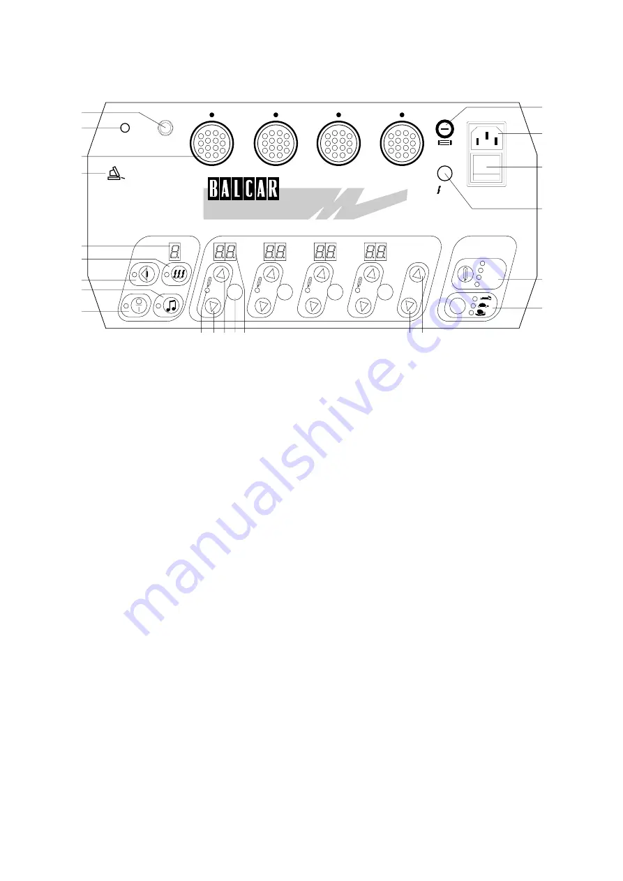
1 A/C Input Plug: Automatic 100-240 V • 50/60 Hz.
2 Fuse holder
3 Main On/Off: shuts all power.
4 Auxiliary on/off: puts the unit on standby.
5 Light Head Plug
Compatible with existing Balcar "PS-U 3/4" and "PS-Z
4" light heads.
The unit automatically senses the presence of the
head.
6 Charge Rate Selector and Indicator (3 Modes)
All positions draw a constant current.
7 Light Head Main Indicator
Will turn on if the light head is plugged in and turned
on.
Indicates the flash power in decimal f-stops.
8 Light Head On/Off
Turns the light head on/off (flash and model lamp) if
the head is connected. Also used to turn individual
model lamps on and off.
9 Head Power Up: controls power and/or model lamp.
10 Head Power Down: controls power and/or model
lamp.
11 Model On/Off Indicator
12 Master Power Up
Raises the power of all heads simultaneously, pre-
serving light ratios, until the maximum on any one
head is reached.
13 Master Power Down
Lowers the power of all heads simultaneously, pre-
serving light ratios, until the minimum on any one
head is reached.
14 Model Lamp Selector
When pressed normally, changes model lamp modes:
• model lamps off (no mode selected)
• Auto: Each model lamp is proportional to the
flash power of each head:
10 is 100%, 9 is 50%, 8 is 25% etc.
• Auto Max: Each model lamp is proportional to
the flash power of each head, but there is always
one model lamp at 100%: the other model lamps
are proportionally lower.
• 100%
• independent: The level of each model lamp is
set using the up (9) and down (10) keys while
maintaining the model lamp selector pressed.
When held pressed, allows individual control of each
model lamp using keys 8, 9 and 10 and displays 7 and
11.
15 Sequencer On/Off
16 Sequence Counter
Used to create multiple flashes, in one of two modes:
• In Automatic (“A”) mode, the flash will trigger as
long as the “Test” button (17) or camera synchro
“X” (18) is held down. The display (16) will count
up.
• In standard mode, the number of flash desired is
selected. A simple trigger will start the sequence.
The display will count down until the sequence is
over.
17 Test Button/100% Charge Indicator
18 Synchro “X” Jack
19 Beep On/Off with Indicator
20 Photocell On/Off with Indicator
21 Photocell
22 LocalTalk™ Interface: connects the pack to a net-
work.
Each head is controlled either individually, or with the
master (which preserves light ratios). Each head can vary
from 10 (full power) to 6.0 (1/16 power) using the up and
down keys, with additional variation on each head: 2 f-
stops (PS-U 4), 1.5 f-stop (PS-Z 4) or 1 f-stop (PS-U 3)
2.
CONTROL PANEL


