Invivo
2
Plus
UM-14 Version R3.0
Page 17
Invivo
2
Plus User Manual
Control system layout
3.3
The control system layout varies by model. Please familiarise yourself with the control system layout
of the Invivo
2
Plus workstation.
Control panel – Standard humidity control
3.3.1
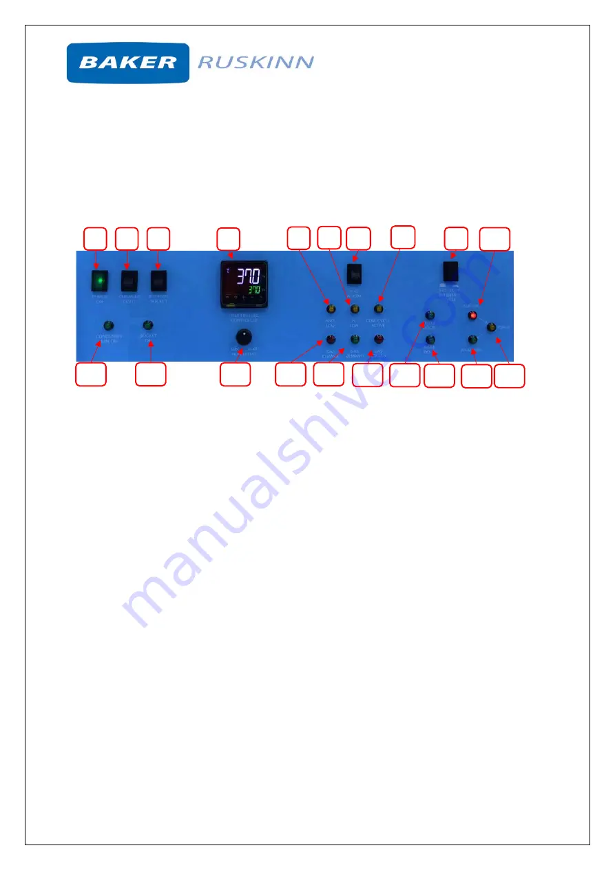
Figure 9 shows the control panel of Invivo
2
Plus workstations equipped with standard humidity
control;
Figure 9: Invivo
2
Plus workstation control panel
1.
Power indicator.
Illuminates to indicate the workstation is connected to the mains power
supply and is switched on.
2.
Chamber light switch.
Press to switch the chamber light on / off. The chamber light switches
off after 1 hour automatically.
3.
Internal socket.
Press to switch the internal socket on / off.
4.
Temperature controller
. See section 3.3.3, for more details.
5.
ANO
2
low.
6.
N
2
low
.
7.
Gas alarm.
Press to switch the gas alarm on / off.
8.
Com. Cycle active.
9.
Interlock purge cycle selector
. Press to switch between the standard (3mins) and economy
(2minutes) interlock cycles. When the switch is depressed, the economy cycle is selected.
Note that this feature is an optional accessory.
10.
Interlock cycle status aerobic indicator.
Illuminates to indicate that the interlock chamber is
in an aerobic condition and requires purging
11.
Interlock cycle status purge indicator
. Illuminates to indicate that the interlock purge cycle
is in progress.
12.
Interlock cycle status anaerobic indicator.
Illuminates to indicate that the interlock chamber
is in an anaerobic condition.
13.
Inner door indicator
. Illuminates to indicate that the interlock inner door is open.
14.
Outer door indicator
. Illuminates to indicate that the interlock outer door is open.
15.
Gas Excess
.
16.
Gas Demand
. Illuminates to indicate a low pressure condition inside the workstation
chamber.
17.
Gas change
18.
Humidistat
. See Sector 4.2 for more details.
1
2
3
4
5
6
7
9
10
8
15
16
14
13
12
11
17
18
19
20


