Consolidated 2700 Series Safety Valve Instruction Manual
| 25
© 2022 Baker Hughes Company. All rights reserved.
XIV. Re-Assembly Instructions (Cont.)
determine the number of notches that the ring is to
be lowered.
9. Once the upper adjusting ring/guide assembly is
properly set, lubricate the guide seating surface
in the valve base, and re-install the assembly into
the base, then lubricate the threads of the upper
adjusting ring pin and lock the ring/guide assembly
in place by installing in the pin.
10. Verify that the upper ring is capable of a slight
movement. If the upper ring does not move, the pin
is too long. Should this be the case, grind the end
of the pin to shorten it, while retaining the original
tip contour, then reinstall the pin.
11. Clamp the spindle in a padded vise, with the “ball
end” of the spindle upward.
12. Verify that the spindle bearing has been ground to
the disc pocket, as specified in Section XII.B.6.e.,
of this manual.
Note:
This step must be accomplished before
proceeding with re-assembly.
13. If the lift stop was removed from the spindle,
lubricate the threads and install the lift stop. Do not
install the cotter pin at this time.
14. If the disc collar was removed, lubricate the
threads and install on the spindle. Do not install
the cotter pin at this time. Then, carefully lower the
disc holder onto the spindle, allowing it to sit on the
face of the disc collar.
15. Place the disc on the spindle, ensuring that the
disc is free to “rock” on the spindle tip as specified
in Section XII.B.6.f., of this manual. If disc “rock”
is not satisfactory, correct the cause before
proceeding.
16. When disc “rock” is satisfactory, remove the disc
and disc holder, and secure the disc collar with
a stainless steel cotter pin. Using side cutters,
carefully cut off excess cotter pin legs, and bend
the cotter pin for a neat installation.
17. Lubricate the spindle tip, and assemble the disc
holder and disc to spindle. Recheck the rock.
18. Remove complete assembly from the vise, being
sure to protect the disc seat surface at all times.
19. Prior to installing the spindle assembly into the
valve base, wipe the disc seat with a soft, lint-free
cloth. Then, carefully install the spindle assembly
into the guide.
20. Lubricate the compression screw threads with
“Fel-Pro Nickel Ease,” and thread into the yoke.
Install the lower washer on the spring and then
install the upper washer on the spring. Lubricate
the bearing assembly with “Fel-Pro Nickel Ease”
and install on the upper spring washer.
21. For orifice sizes 5-Q, place the compression screw
adaptor on top of the bearing.
22. Place the spring and bearing assembly into the
yoke.
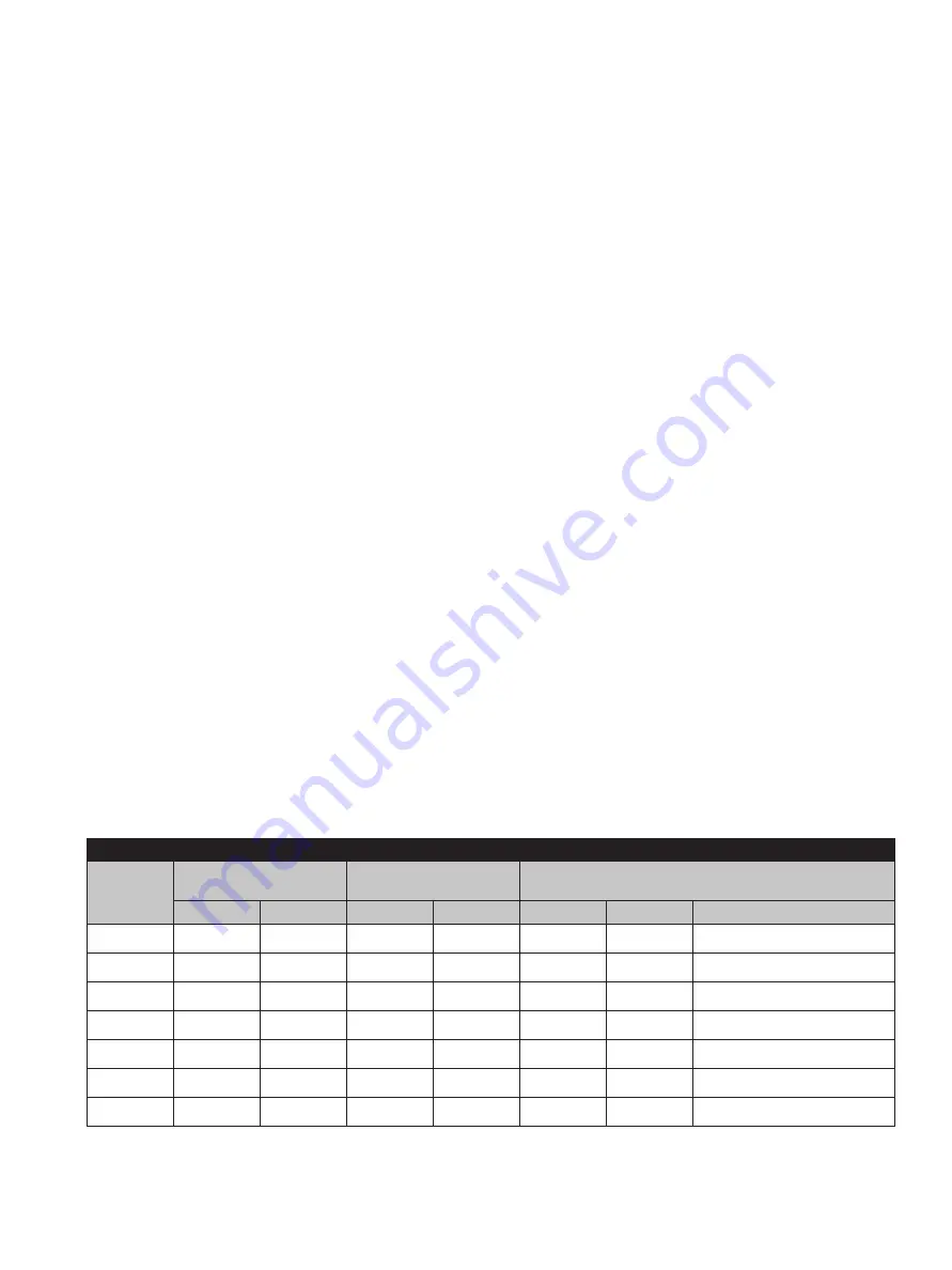
Table 8: Required Lift for Capacity Verification
Orifice
Capacity Lift
Required Additional
Lift
Total Lift
1 & 2
in.
mm
in.
mm
in.
mm
1
.281
7.14
.020
0.51
.301
7.65
Approx. 31 Notches
2
.338
8.59
.020
0.51
.358
9.09
Approx. 36 Notches
3
.450
11.43
.030
0.76
.480
12.19
Approx. 48 Notches
5
.516
13.11
.050
1.02
.566
14.12
Approx. 62 Notches
4
.563
14.30
.040
1.27
.603
15.57
Approx. 56 Notches
6
.750
19.05
.060
1.52
.810
20.57
Approx. 81 Notches
Q
.987
25.07
.070
1.78
1.057
26.85
Approx. 106 Notches
1. For full lift valves only.
2. Total lift tolerance is
+ .020” + 0.51 mm
- .000” - 0.00 mm
[
]
. Per the ASME Section I code, the valve lift must be mechanically verified
and shall meet or exceed the required lift.


