


Copyright 2020 Baker Hughes Company. All rights reserved.
Page 141 of 277
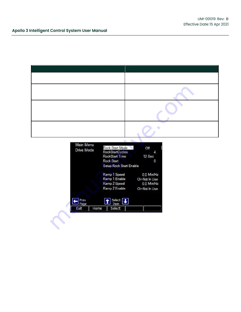
Drive Mode include:
Table 34: Drive Mode Menu
Mode
Description
ManualFrequency
Manual Frequency Control Mode. Control mode in
which the drive runs at a programmable speed.
CurrentControl
Current Control Mode. Control mode in which the
drive speed is automatically varied in an attempt to
provide a fixed output current.
PID Speed Ctrl
PID Speed Control Mode. Control mode in which
the drive speed is automatically varied in an attempt
to keep a system parameter (referred to as the
control parameter) at a specified level.
Analog Follower
Analog Follower Control Mode. Control mode in
which the drive speed is based on a scaled analog
input.
Figure 119: Drive Mode Menu-Screen 2
Summary of Contents for Apollo 3
Page 1: ...Copyright 2020 Baker Hughes Company All rights reserved Page 1 of 277...
Page 266: ...Copyright 2020 Baker Hughes Company All rights reserved Page 266 of 277 Figure 227 USB Menu...
Page 267: ......
Page 276: ......
Page 277: ...Index 129112 28 197705 28 197349 28 800638 28 197350 28 810280 28 197351 29...


