background image


BA RoofOn V30 R16 12_2012 GB mit CE BAK.doc 


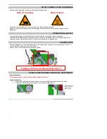
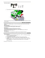
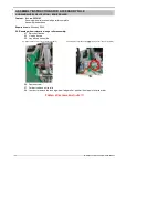
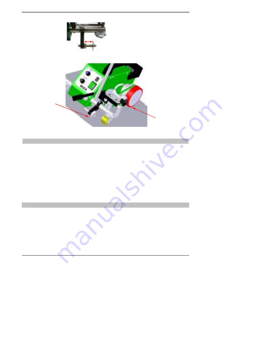
Guide roller adjustment:


Space  

for 

welding 

line with 

10mm 


20mm 

20mm 


30mm 

30mm 


40mm 


Bring the welding machine into the right welding position. 


Outside edge of the overlap, outside edge of the pressure roller and outside edge of the guide roller must form 
a line (see image). 


WELDING PARAMETERS 


Caution: 

Before any welding operation, a test weld should be performed so as to determine the welding 

parameters. 


Welding temperature: 

The welding temperature is adjusted with a potentiometer or control unit. 
Do not start welding before the set temperature has been reached. 


Welding speed: 

The welding speed is adjusted using a potentiometer or control unit. 
The drive starts automatically when the welding machine is swivelled in. 
The welding speed is adjusted with the potentiometer or control unit depending on the plastic film, 
geomembrane liner or weather conditions. 


Welding pressure:


The welding pressure is directly applied onto the pressure roller by the weight of the machine. 


WELDING 


Operating conditions: 


Maintain the maximum allowed network impedance (Z

max

 = 0.301 Ω + j 0.188 Ω) and consult your 

local electricity supply board if necessary. 


Check the configuration of the nozzle. 


The mains connection must conform to ICE 60364 as well as to national standards. 


Connect the device to the grid. The voltage rating must correspond to the specifications on the 

nameplate. 


When using extension cords, a minimum diameter of the cable must be observed. Cable length up 

to 25 m, diameter 2.5 mm² (for automatic welding machines with 120 V, we recommend a 
diameter of 4.0 mm²). 


Summary of Contents for ROOFON

Page 1: ...OPERATING MANUAL BA RoofOn V30 R16 12_2012 GB mit CE BAK doc RoofOn RoofOn R Edge...

Page 2: ...rotection the device must be connected to a residual current circuit breaker before using it on construction sites Do not leave the device unobserved Hot air radiation of the hot air device may ignite...

Page 3: ...or when advised how to use the device by that person Children must be supervised in order to ensure that they do not play with the device Because of the enormous fire danger the operating personnel mu...

Page 4: ...ed risks to the life and health of the operating personnel when the machine is used in accordance with its intended use DANGER ZONE The main danger zone of the welding machine is the nozzle which can...

Page 5: ...rive starts automatically when the welding machine is swivelled in The welding speed is adjusted with the potentiometer or control unit depending on the plastic film geomembrane liner or weather condi...

Page 6: ...NCE AND SUPPORT The HERZ group and its authorised service centres offer free support and assistance in the area of applications technology Our specialists will be pleased to help you ACCESSORIES Avail...

Page 7: ...elivery by the carrier The seller must be promptly informed in writing Storage In the case of temporary storage the welding machine should be kept packed and must be protected from moisture In the cas...

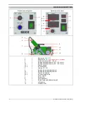
Page 8: ...stment 50 100 4 Welding speed adjustment 0 6 12 5 m min 4 1 Welding speed adjustment 0 6 12 5 m min 4 1 1 Reduce speed 4 1 2 Increase speed 5 Heating ON OFF 6 Welding temperature adjustment 6 1 Weldin...

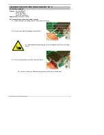
Page 9: ...Allen keys SW3 5 8 0 Assembly instructions for additional weight 8 1 Switch off the device unplug it and let it cool down if necessary 8 2 Screw out the M6x10 threaded bolt Allen SW3 8 3 Add additiona...

Page 10: ...uired tools Allen key SW6 9 0 Running wheel relocation edge roller assembly 9 1 Switch off device 9 2 Unplug device 9 3 Lay device on its side 9 4 Remove Allen screw of the guide handle SW6 9 5 Assemb...

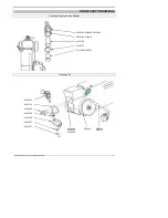
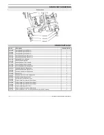
Page 11: ...SPARE PARTS DRAWINGS Heating element and tube adapter Lifting device 5230043 5230044 5230045 5230169 5202010 6101760 5101270 5113269 5113267 5230054 5230112 5280284 5230036 5230055 5230037 5230097 51...

Page 12: ...054 Push rod tightener for lifting device 1 5230112 Fastening angle for lifting device 1 5280284 Rounded head screw M5x20 Torx 3 5230036 Centring push rod for lifting device 1 5230055 Guide roller 3 5...

Page 13: ...3 3 2008 EN61000 6 2 2005 EN61000 6 4 2007 A1 2011 EN60335 1 2012 _____________________________ Mag Marion Herz Degenkolb Gerente Sch nberg 30 01 2011 Portugu s Declara o de conformidade HERZ GmbH A...

Page 14: ...007 A1 2011 EN60335 1 2012 _____________________________ Mag Marion Herz Degenkolb ener ldirektors Sch nberg 30 01 2011 Dansk Conformiteitsverklaring HERZ GmbH A 6141 Sch nberg Austria bekr fter at de...

Page 15: ...ag Marion Herz Degenkolb Sch nberg 30 01 2011 Norsk Deklaration av samsvarsm ling fra HERZ GmbH A 6141 Sch nberg bekrefter at denne modellen av v rt solgte produkt oppfyller kravene i f lgende EF dire...

Page 16: ...16 BA RoofOn V30 R16 12_2012 GB mit CE BAK doc...

Reviews: