DESCRIPTION AND OPERATION
HSS MODULE CIRCUITRY
I-E96-322A
2 - 7
Microprocessor
The HSS module uses a 16-bit microprocessor to control board
functions and communicate with the MFP module through the
I/O expander bus interface. The microprocessor controls the
analog-to-digital processing, passes position feedback and sta-
tus information to the MFP module, reads control data from
the MFP module, writes position demands to the D/A converter
and does self checks.
The microprocessor also controls the hard manual circuit. This
circuit provides isolated contacts the user connects to 24 VDC,
giving the operator a way to initiate control of the hydraulic
actuator in the event the MFP module communications is lost.
By activating the raise or lower contacts, the operator tells the
microprocessor to change the actuator position. The micropro-
cessor also writes to a digital output to tell the operator the
module is in the hard manual mode of operation.
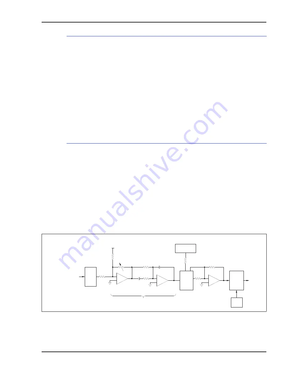
Position Demand and Output
There are four parts to the position demand and output block:
•
D/A converter.
•
Position error.
•
Servo amplifier.
•
Dither oscillator.
The output circuit provides proportional plus integral plus
derivative (PID) closed loop control on the entire servo valve
system. Additionally, the microprocessor reads servo status
and selects which servo to output to through this output block.
Figure
shows a simplified diagram of the position demand
and output circuit.
Figure 2-3. Position Demand and Output Circuit
TP25409A
+
-
DITHER
OSCILLATOR
SWITCH
SERVO
DRIVE
OUTPUTS
DAC
SERVO AMP
POSITION ERROR
PROPORTIONAL
AMP
+
-
+
-
INTEGRAL AND
DERIVATIVE AMP
SWITCH
TRIP
BIAS
POSITION FEEDBACK
FROM
DEMODULATOR
POSITION
DEMAND
FROM
MICROPROCESSOR


