


35
35
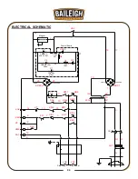
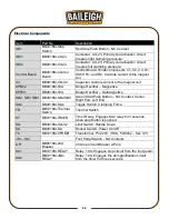
Electrical Components
Item
Part No.
Description
SB1
BB7216M-Stop
Switch
Red Stop Push Button - NC Contact
KM1
BB9616M-CU23
Contactor, CU-23, Primary coil activation circuit.
Creates light clamping pressure.
KM2
BB9616M-CU23
Contactor, CU-23, Primary coil activation circuit.
Creates full clamping pressure.
Control Board
BB4816M-Control
Board
Control Board, Holds components C1, C2, C3, D1,
KS50, R1, and R2. Controls current to the magnet
coil.
C4
BB4816M-CB-C4
Capacitor controls current to the magnet coil.
KPBC2
BB9616M-50A
Bridge Rectifier
– Magnetize
KPBC1
BB9616M-50A
Bridge Rectifier
– De-Magnetize
SB2, SB3, SB4 BB4816M-SB2,SB3
Green Start Push Button
– NO Contact, Center,
Right End, Left End
SA2
BB4816M-SA2
Toggle Switch, Clamping Force
FR
BB7216M-Thermal
Switch
Thermal Switch
KT
BB7216M-TIMER
Timer Relay, Engages KA2 relay for 3 seconds
when stop button is pushed.
SQ
BB4816M-SQ-V2
Limit Switch, Handle Down
SA
BB4816M-SA
Rocker Switch, Power On/Off
TC
BB7216M-XFRMR
Transformer, Pri.220V, 30VA, 50/60hz
– Sec.12V
JK1, JK2
Foot Pedal Switch - NO Contacts
QF1
BB9616M-20A
Breaker
20 Amp Circuit Breaker 2-Pole
KA1
BB7216M-RELAY
Relay, 10A, Engages stop circuit from the foot pedal.
KA2
BB7216M-JQX-
RELAY
Relay, 10A, Engages the demagnification circuit
from the timer for three seconds.
Summary of Contents for BB-7216M
Page 12: ...10 10 4 1 2 3 3...
Page 16: ...14 14 OVERALL DIMENSIONS...
Page 31: ...29 29 PARTS DIAGRAM...


