background image

27 

27 

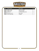
Parts List 

Item 

Part Number 

Description 

Qty. 

MH19-5D001-V2 

Stand Assembly 

PP-1310 

Electrical Box 

PP-0304 

On/Off 2 Pole Switch 

MH19-6A025 

Box Mount (Short) 

MH19-6A026 

Box Mount (Long) 

PP-0023 

Cord Grip 

PP-0025 

Cord Grip 

5/16 LOCK WASHER 

Imperial 

10 

5/16-18 x .75 

HHCS 

10 

PP-0823 

Rubber Standoff Peg 

11 

5/16-18 HEX NUT 

Imperial 

12 

PP-0895 

Rubber Grommet 

24 

13 

PP-0919 

Leveling Pad 

14 

3/4-10 HEX NUT 

Imperial 

15 

MH19-6D009 

Right Side Frame 

16 

1" LOCK WASHER 

Imperial 

14 

17 

1.0-8 X 4.5 

HHCS 

18 

MH19-7A002 

Frame Spacer 

19 

MH19-7A012 

Trunnion 

20 

MH19-6A006 

Bottom Die Holder 

21 

MH19-6A007 

Top Slide Block 

22 

PP-1548 

1.5 Bore Cartridge Bearing 

23 

PP-0825 

Slide Block Bushing 

24 

MH19-7A004 

Main Slide 

25 

MH19-7A019 

Lower Die Mount 

26 

MH19-6A066 

Short Link 

27 

MH19-7A034 

Lock Pin 

28 

PP-0144 

1.0 ID x 1.25 OD x 1.0 Long 

29 

PP-0935 

1.0 ID x 1.5 OD x .0625 THK 

30 

.25-20 x .75 

SHCS 

31 

STD 

.5 Lock Washer 

31 

32 

1/2-13 x 1.75 

HHCS 

20 

33 

MH19-7A008 

Pivot Bushing 

Summary of Contents for B8935

Page 1: ...OPERATOR S MANUAL POWER HAMMER MODEL MH 19 B8935 2015 Baileigh Industrial Inc Rev 04 2015...

Page 2: ...Wheel Mode 15 MATERIAL SELECTION 16 LUBRICATION AND MAINTENANCE 16 PARTS DIAGRAM 17 Stand Frame Assembly Parts Diagram 17 Slide Block Assembly Parts Diagram 18 Pulley Assembly Parts Diagram 19 Cranks...

Page 3: ...rect installation guidelines Description of the functional parts of the machine Capacity charts Set up and start up instructions Machine operation Scheduled maintenance Parts lists GENERAL NOTES After...

Page 4: ...afety alert symbol DANGER identifies a hazard or unsafe practice that will result in severe Injury or Death Safety signs with signal word DANGER or WARNING are typically near specific hazards General...

Page 5: ...machinery PROTECT AGAINST NOISE Prolonged exposure to loud noise can cause impairment or loss of hearing Wear suitable hearing protective devices such as ear muffs or earplugs to protect against objec...

Page 6: ...tools Before operating the machine make sure any adjusting tools have been removed 4 Keep work area clean Cluttered areas invite injuries 5 Overloading machine By overloading the machine you may cause...

Page 7: ...en away Children must never be allowed in the work area DO NOT let them handle machines tools or extension cords 16 Store idle equipment When not in use tools must be stored in a dry location to inhib...

Page 8: ...50hz 10A Motor 240V 2Hp 1 5kw Shipping Weight 1600lbs 726kgs Shipping Dimensions 60 x 60 x 84 1524 x 1524 x 2134mm Note The photos and illustrations used in this manual are representative only and may...

Page 9: ...damage painted surfaces Follow manufacturer s label instructions when using any type of cleaning product After cleaning wipe unpainted metal surfaces with a light coating of quality oil or grease for...

Page 10: ...lts that attach the machine to the pallet Approaching the machine from the side lift the machine on the frame taking care that there are no cables or pipes in the area of the forks Move the machine to...

Page 11: ...LING The machine should be sited on a level concrete floor Provisions for securing it should be in position prior to placing the machine The accuracy of any machine depends on the precise placement of...

Page 12: ...event of a malfunction or breakdown grounding provides a path of least resistance for electric current to reduce the risk of electric shock This tool is equipped with an electric cord having an equip...

Page 13: ...G 25ft 50ft 100ft 0 6 16 16 16 7 10 16 16 14 11 12 16 16 14 13 16 14 12 12 17 20 12 12 10 21 30 10 10 No WIRE GAUGE An undersized cord decreases line voltage causing loss of power and overheating All...

Page 14: ...ontrol box The foot control fully depressed will max out at whatever the limiting potentiometer is set to 1 To set the machine to power hammer mode the control box must be turned in the off position 2...

Page 15: ...n feed lock lever G and rotate the down feed hand wheel H until the gap between the tools is about 1 4 This is where most dies work the best Make sure all lock levers are tight and the quick release p...

Page 16: ...nd bolted rigid This mode is used for short stroke tooling such as beading flanging mechanical shrinking mechanical stretching etc 1 To set the machine in this mode turn the control switch to Off 2 Lo...

Page 17: ...e tooling and quick release pins 5 Now you can install the upper wheel assembly The down feed may need to be adjusted down to gain enough clearance for the wheel assembly It is best if two people do t...

Page 18: ...ed components and sliding devices Apply rust inhibitive lubricant to all non painted surfaces There are 7 grease fittings on the machine Grease these fittings every month with two pumps from a standar...

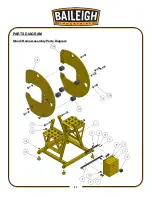
Page 19: ...17 17 PARTS DIAGRAM Stand Frame Assembly Parts Diagram...

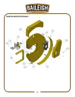
Page 20: ...18 18 Slide Block Assembly Parts Diagram...

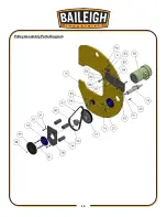
Page 21: ...19 19 Pulley Assembly Parts Diagram...

Page 22: ...20 20 Crankshaft Assembly Parts Diagram...

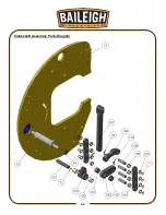
Page 23: ...21 21 Clevis Shaft Assembly Parts Diagram...

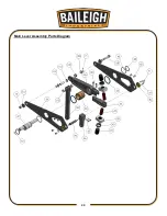
Page 24: ...22 22 Bell Crank Assembly Parts Diagram...

Page 25: ...23 23 Main Lever Assembly Parts Diagram...

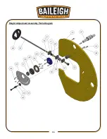
Page 26: ...24 24 Height Adjustment Assembly Parts Diagram...

Page 27: ...25 25 Left Hand Frame Assembly Parts Diagram...

Page 28: ...26 26 Guard Assembly Parts Diagram...

Page 29: ...ling Pad 4 14 3 4 10 HEX NUT Imperial 5 15 MH19 6D009 Right Side Frame 1 16 1 LOCK WASHER Imperial 14 17 1 0 8 X 4 5 HHCS 4 18 MH19 7A002 Frame Spacer 5 19 MH19 7A012 Trunnion 1 20 MH19 6A006 Bottom D...

Page 30: ...07 Height Eccentric 1 48 2 5 EXT RETAINING RING Imperial 2 49 MH19 7A009 40 Tooth Worm Gear 1 50 MH19 7A006 Gear Hub 1 51 MH19 6A028 Worm Shaft Block 3 52 MH19 7A024 Lock Spacer 1 53 1 2 13 x 1 25 SHC...

Page 31: ...1 5 HHCS 7 82 MH19 6C022 Motor Mount 1 83 MH19 6A024 Jack Screw Block 1 84 1 LOCK WASHER Imperial 1 85 3 4 FLAT WASHER Imperial 1 86 3 4 LOCK WASHER Imperial 1 87 1 8 x 2 5 HHCS 1 88 3 4 10 x 2 0 HHCS...

Page 32: ...ID x 1 5 OD x 125 THK 1 117 MH19 7A014 Pin Bushing 2 118 MH19 7A025 Shear Bolt 1 119 MH19 7A033 Pilot Pin 1 120 MH19 7A057 Crank Nut 1 121 MH19 7A032 Pivot Pin 1 122 MH19 6A030 Shaft Keeper 2 123 MH1...

Page 33: ...Panel 1 153 MH19 6A042 ARC Rear Guard 1 154 MH19 6A041 Inside Guard 1 155 HAND KNOB DK 1216 1 156 3125 18 KNOB Auto Stop Knob 2 157 PP 1492 Tooling Pin 2 158 PP 0831 Switch Box 1 159 PP 0044 Potentiom...

Page 34: ...32 32 Item Part Number Description Qty 174 MH19 7A020 Hex Drive Collar 1 175 MH19 7A037 Pressure Shaft 1 176 PP 0138 1 25 Set Screw Collar 2 177 5 16 18 x 375 Set Screw 1 178 3 4 16 HEX NUT Imperial 1...

Page 35: ...33 33 NOTES...

Page 36: ...34 34...

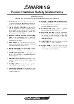
Page 37: ...the off position before re connecting 14 Use correct amperage extension cords Undersized extension cords overheat and lose power Replace extension cords if they become damaged 15 Keep machine well ma...

Page 38: ...anglement with moving parts 7 Understand the machines controls Make sure you understand the use and operation of all controls 8 Warning Labels Take note of any warning labels on the machine and do not...

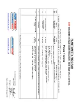
Page 39: ...entification Power Hammer STRIKING O Recommended for Purchase Buyer User Power hammer must be used with extreme precaution and in a controlled enviroment Assessment Hazard Risk Control Strategies Wear...

Reviews: