background image


12 

12 

INSTALLATION 

IMPORTANT: 

Consider the following when looking for a suitable location to place the machine: 

  Overall weight of the machine. 

  Weight of material being processed. 

  Sizes of material to be processed through the machine.


  Space needed for auxiliary stands, work tables, or other machinery.


  Clearance from walls and other obstacles.


  Maintain an adequate working area around the machine for safety. 

  Have the work area well illuminated with proper lighting. 

  Keep the floor free of oil and make sure it is not slippery. 

  Remove scrap and waste materials regularly, and make sure the work area is free from 

obstructing objects.


  If long lengths of material are to be fed into the machine, make sure that they will not extend 

into any aisles.


LEVELING:

 The machine should be sited on a level, concrete floor. Provisions for securing it 

should be in position prior to placing the machine. The accuracy of any machine depends on 
the precise placement of it to the mounting surface. 


FLOOR:

 This machine distributes a large amount of weight over a small area. Make certain 

that the floor is capable of supporting the weight of the machine, work stock, and the 
operator. The floor should also be a level surface. If the unit wobbles or rocks once in place, 
be sure to eliminate by using shims. 


WORKING CLEARANCES: 

Take into consideration the size of the material to be 

processed. Make sure that you allow enough space for you to operate the machine freely. 


POWER SUPPLY PLACEMENT: 

The power supply should be located close enough to the 

machine so that the power cord is not in an area where it would cause a tripping hazard. Be 
sure to observe all electrical codes if installing new circuits and/or outlets. 

Anchoring the Machine 

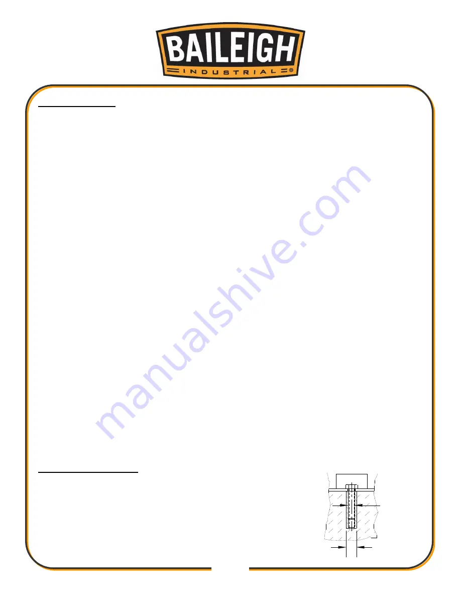
  Once positioned, anchor the machine to the floor, as shown in 

the diagram. Use bolts and expansion plugs or sunken tie rods 
that connect through and are sized for the holes in the base of 
the stand. 

  This machine requires a solid floor such as concrete at a 

minimum of 4” (102mm) thick. 6” (153mm) minimum is preferred. 

.31"

(7.87mm)

.50"

(12.7mm)

Summary of Contents for AS-350M

Page 1: ...TRIAL HOLDINGS LLC IS PROHIBITED Baileigh Industrial Holdings LLC Inc does not assume and hereby disclaims any liability for any damage or loss caused by an omission or error in this Operator s Manual...

Page 2: ...LLATION 12 Anchoring the Machine 12 OVERALL DIMENSIONS 13 GETTING TO KNOW YOUR MACHINE 14 ASSEMBLY AND SET UP 17 ELECTRICAL 18 OPERATION 20 Miter Angle 20 Vise Operation 20 Loading Material 21 Setting...

Page 3: ...n notice to Seller of any suspected defect in the Goods prior to the expiration of the warranty period The original end user must also obtain a RGA from Seller prior to returning any Goods to Seller f...

Page 4: ...emedies provided under this Agreement or at law or equity Attorney s Fees In the event legal action is necessary to recover monies due from Buyer or to enforce any provision of this Agreement Buyer sh...

Page 5: ...Description of the functional parts of the machine Capacity charts Setup and start up instructions Machine operation Scheduled maintenance Parts lists GENERAL NOTES After receiving your equipment remo...

Page 6: ...zardous situation which if not avoided will result in death or serious injury WARNING Indicates a hazardous situation which if not avoided could result in death or serious injury CAUTION Indicates a h...

Page 7: ...gainst objectionable or uncomfortable loud noises DUST HAZARD Wear appropriate dust mask Dust created while using machinery can cause cancer birth defects and long term respiratory damage Be aware of...

Page 8: ...personal injury However if normal safety precautions are overlooked or ignored personal injury to the operator may result Safety equipment such as guards hold downs safety glasses dust masks and hear...

Page 9: ...l tool or attachment to do the work of a large industrial tool DO NOT use a tool for a purpose for which it was not intended 10 Dress appropriate DO NOT wear loose fitting clothing or jewelry as they...

Page 10: ...r replacing any torch parts 25 Be sure all equipment is properly installed and grounded according to national state and local codes 26 Keep all cords dry free from grease and oil and protected from sp...

Page 11: ...nt can be reached at 920 684 4990 and asking for the support desk for purchased machines Tech Support handles questions on machine setup schematics warranty issues and individual parts needs other tha...

Page 12: ...age painted surfaces Follow manufacturer s label instructions when using any type of cleaning product After cleaning wipe unpainted metal surfaces with a light coating of quality oil or grease for pro...

Page 13: ...to the floor Level the machine so that all the supporting feet are taking the weight of the machine and no rocking is taking place Follow these guidelines when lifting crane or hoist Always lift and c...

Page 14: ...the precise placement of it to the mounting surface FLOOR This machine distributes a large amount of weight over a small area Make certain that the floor is capable of supporting the weight of the ma...

Page 15: ...13 13 OVERALL DIMENSIONS...

Page 16: ...14 14 GETTING TO KNOW YOUR MACHINE B G A I H L C E D F M K J...

Page 17: ...piece part I Motor belt guard Contains belts and shields pinch points J Stop bar For setting the length of cut K Front and rear jaw For clamping piece part L Vise hand wheel Turning hand wheel opens...

Page 18: ...the miter system vise system and head assembly Vise A clamping system which provides the basic support and grip for the work material A hand wheel opens and closes the vise jaws Stand Support structur...

Page 19: ...cw into the drive shaft hub The keyslot for the cable should face down or towards the operator Tighten the jam nut Slide the trigger switch handle O onto the handle rod so the cable exits the keyslot...

Page 20: ...n low voltage will damage the motor In the event of a malfunction or breakdown grounding provides a path of least resistance for electric current to reduce the risk of electric shock This machine is e...

Page 21: ...nd route the cord away from the machine toward the power supply a Route the power cord so that it will NOT become entangled in the machine in any way b Route the cord to the power supply in a way that...

Page 22: ...y clamp and unclamp pieces of the same width Clockwise cw to clamp the piece Counter clockwise ccw to unclamp the piece CAUTION Always wear proper eye protection with side shields safety footwear and...

Page 23: ...th Setting the cut length eliminates measuring duplicate pieces Measure and mark the length of material to be cut off Load the piece part Line up the cut Clamp the piece part Loosen the hand knob at t...

Page 24: ...e feed handle H applying a steady and constant pressure After cut off raise feed handle slowly Release the trigger switch G to stop the blade motor Use vise hand wheel to open the jaws Remove or advan...

Page 25: ...easily Dimensional properties of material must be consistent and not exceed the machine capacity values Chemical structure of material must be consistent Buy certificated steel from the same vendor wh...

Page 26: ...t may have accumulated inside the guard Install the new blade onto the spindle Place washer R and the nut on the spindle note how nut pilots into the washer While holding blade tighten nut countercloc...

Page 27: ...ant to all non painted surfaces Weekly Maintenance Thoroughly clean the machine Clean and grease the vise screw and sliding surfaces Clean the guard housing for the saw blade Monthly Maintenance Check...

Page 28: ...ch the plug from the electrical supply panel Clean and grease the machine Cover the machine CHOOSING A SAW BLADE To achieve a quality economical and efficient saw cut the following points must be take...

Page 29: ...27 27 ELECTRICAL SCHEMATIC...

Page 30: ...28 28 PARTS DIAGRAM...

Page 31: ...Circlip 45 1 11 Blade guard 1 12 Blade guard 1 13 Bolt M8X35 2 14 Bolt M10X70 1 15 Nut M10 1 16 Motor 1 17 Key 8x30 2 18 Block bolt M8X12 3 19 Wheel 1 20 Bolt M10X25 10 21 Washer 10 8 22 Base 1 23 Bol...

Page 32: ...1 45 Blade 1 46 Cover 1 47 Nut 1 48 Key 2 49 Bushing 1 50 Rotary arm 1 51 Flanged shaft 1 52 Shaft 1 53 Lock bolt M8X8 1 54 Lower vise 1 55 Vise plate 1 56 Vise plate 6 57 Bolt M10X50 1 58 Spring wash...

Page 33: ...tem Description Spec Qty 69 Lock ring 1 70 Lock handle 1 71 Bearing 1 72 Bearing cover 1 73 Handle 1 74 Washer 1 75 Bolt M8X35 1 76 Lock bolt M6X10 2 77 Base 1 78 Shaft 1 79 Lock handle 1 80 Nut 1 81...

Page 34: ...nd reason for blown fuses and replace Clear problem and twist button to reset EXCESSIVE BOUNCING OR BREAKING OF THE BLADE Damaged saw blade edge Using excessive down force on the blade Replace the bla...

Page 35: ...33 33 NOTES...

Page 36: ...TOWOC WI 54220 PHONE 920 684 4990 FAX 920 684 3944 www baileigh com BAILEIGH INDUSTRIAL HOLDINGS LTD UNIT D SWIFT POINT SWIFT VALLEY INDUSTRIAL ESTATE RUGBY WEST MIDLANDS CV21 1QH UNITED KINGDOM PHONE...

Reviews: