

52
52
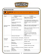
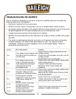
TROUBLESHOOTING THE INVERTER
Prior to operating or adjusting any electronic component, qualified personnel must take the
following aspects into consideration:
•
Disconnect machine from the power supply.
•
DO NOT use bare hands or metal tools to remove or install sensitive electronic parts.
•
As residual voltage still exists in the capacitor after the voltage has been turned off, wait until
the light disappears from the lighted display before proceeding with any work.
•
Visually inspect the electronic circuit board for any defects.
•
NEVER connect the alternating current directly to the output connector (U/V/W) of the speed
controller.
•
The electronic self-diagnosis program can notify you of situations like motor overloading,
voltage fluctuations, etc. When the program detects an error, the machine will stop
immediately, and the error will be displayed on the inverters digital display. Follow the
solutions to correct any errors.
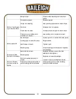
Code
Error Description
Solution
O.C.
The voltage inverter detects that
the output current exceeds the
normal value.
Check if motor voltage matches that of the
voltage inverter.
Check connection between the motor and the
voltage inverter.
Check if the motor is overloaded.
O.U.
The voltage inverter of the
motor is detected with a D.C.
high voltage lateral pressure
value that exceeds the
acceptable range.
Check if the circuit input voltage matches that
of the voltage inverter.
Frequent on/off and forward/reverse
directions result in high voltage self-
protection.
O.H.
The touch pole cooling device of
the motor voltage inverter
indicates an overheat condition.
Check if the circuit input voltage matches that
of the voltage inverter.
Make sure the cooling device is free from dirt
and foreign objects.
O.L.
The frequency converter
detected an output exceeding
150% above normal for 1
minute.
Check if the motor is overloaded.
Tooling may be dull. Check for proper sized
tooling, gear speed, and feed rate.
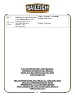
o.c.A
o.c.d
o.c.n
Electric current is too large
during acceleration.
Electric current is too large
during deceleration.
Electric current is too large
during normal operation.
Check if the output connection of the motor
adjuster is insulated improperly.
Summary of Contents for DP-1000VS
Page 19: ...16 16 OVERALL DIMENSIONS ...
Page 20: ...17 17 GETTING TO KNOW YOUR MACHINE Q F P J B C A G H I L M E F D N O K R ...
Page 35: ...32 32 A6 2 A6 3 A6 1 A6 4 A8 1 A8 2 A5 A5 1 A33 1 A19 1 A33 ...
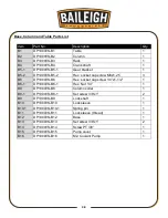
Page 39: ...36 36 BASE COLUMN AND TABLE PARTS DIAGRAM B1 B2 B11 B10 B9 B10 1 ...
Page 40: ...37 37 B3 B4 B6 1 B6 B5 1 B5 2 B8 B8 1 B12 B13 B16 B15 B14 ...
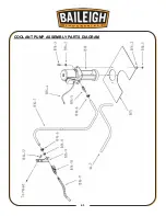
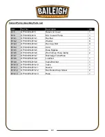
Page 44: ...41 41 COOLANT PUMP ASSEMBLY PARTS DIAGRAM ...
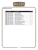
Page 46: ...43 43 CONTROL PANEL PARTS DIAGRAM ...
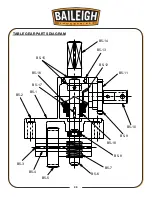
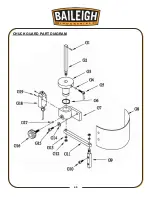
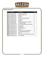
Page 48: ...45 45 CHUCK GUARD PART DIAGRAM ...


