


25
25
Material Removal
1. After reaching the desired angle, the material needs to be removed.
2. Press the reverse (left) foot pedal. Both the die and the counter die will retract
simultaneously. Run in reverse until all bending pressure is released from the bend.
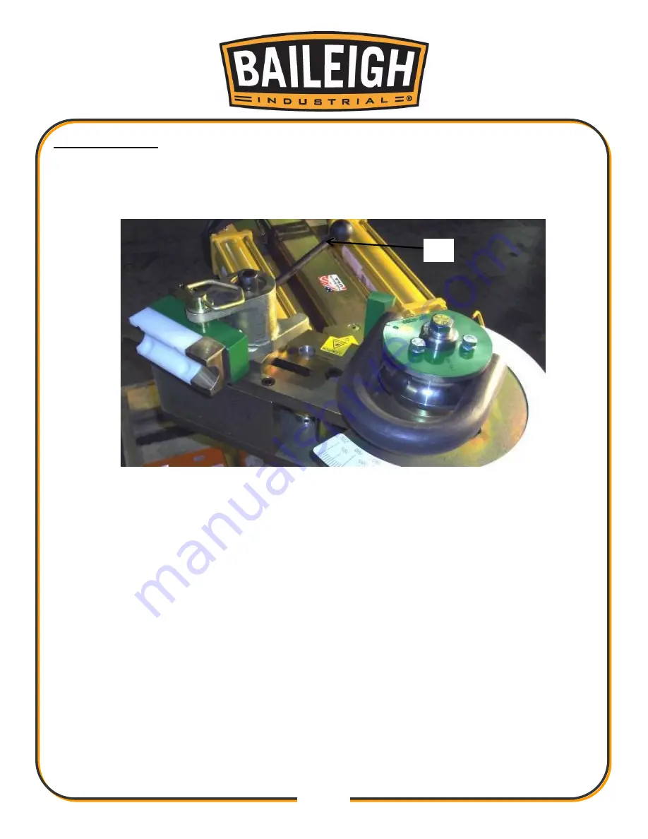
Activating the quick release lever
3. Activate the quick release counter die lever (A) and completely remove the material.
4. After the material is safely removed, press the reverse (left) foot pedal keeping hands clear
until both cylinders fully retract.
5.
The machine is now at the “home” position and can be reloaded for the next bend.
6. Repeat previous steps.
A
Summary of Contents for 1006778
Page 17: ...14 14 GETTING TO KNOW YOUR MACHINE A B C D E F H I J K L G...
Page 38: ...35 35 RDB 150 ELECTRICAL SCHEMATIC...
Page 39: ...36 36 RDB 150 AS ELECTRICAL SCHEMATIC...
Page 46: ...43 43 Diagram 1...
Page 47: ...44 44 Diagram2...
Page 48: ...45 45 PARTS DIAGRAM Power Unit and Cart Assembly Parts Diagram...
Page 49: ...46 46 Main Tube and Cylinders Assembly Parts Diagram...
Page 50: ...47 47 Swing Arm Assembly Parts Diagram...
Page 51: ...48 48 Degree Dials Parts Diagram...
Page 56: ...53 53 Hydraulic System Parts Diagram...
Page 58: ...55 55 NOTES...
Page 59: ...56 56 NOTES...