background image


Figure 1-1 EG7035E Appearance 


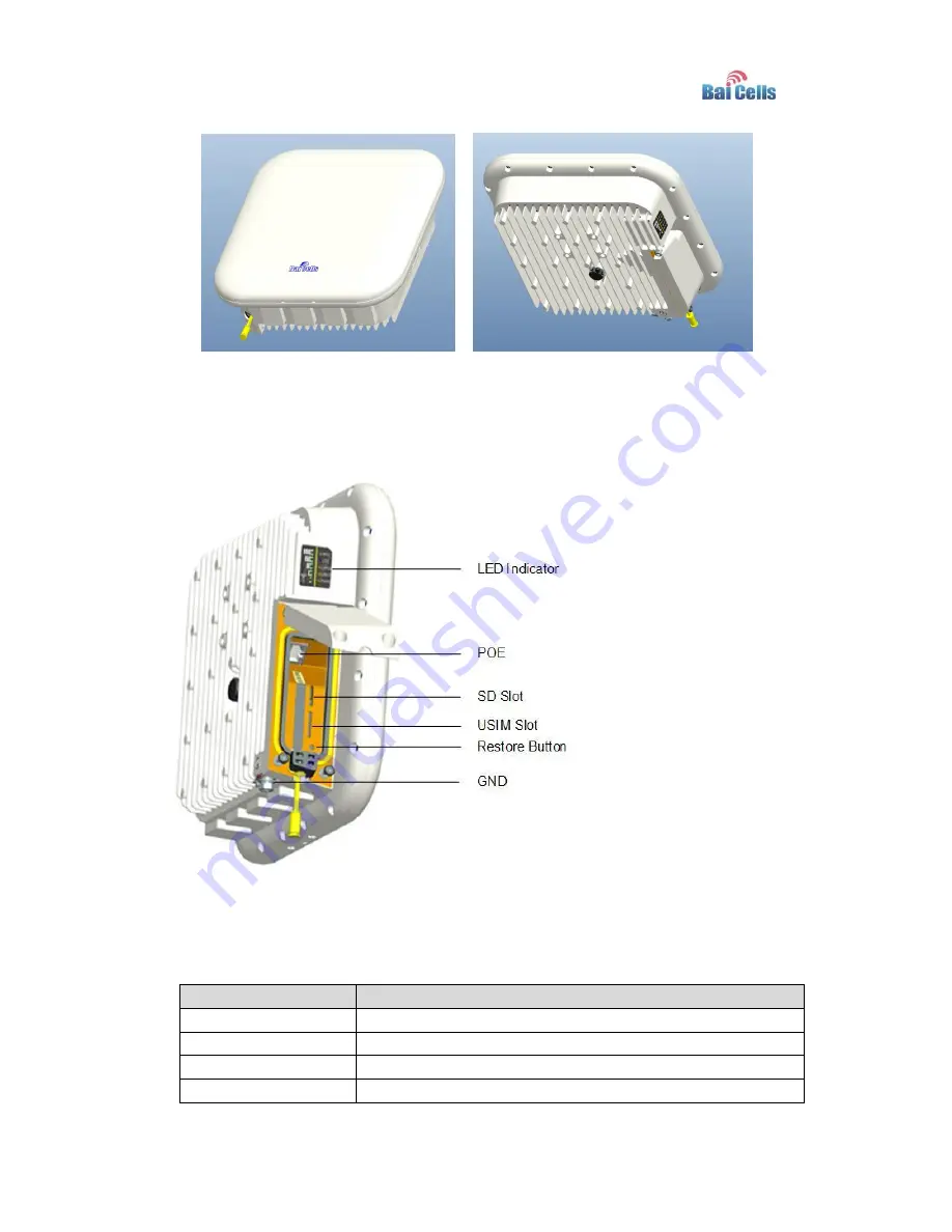
The EG7035E interfaces and buttons are shown in Figure 1-2. 

Figure 1-2 Interface and Button of EG7035E 


The EG7035E interface and button description is given in Table 1-1. 

Table 1-1 Description of EG7035E Interface and Button 

Interface & Button 

Description 

PoE 

Connected to the PoE power adapter 

SD slot 

Support SD card 

USIM Slot 

Support 1.8V/3.0V USIM 2FF 

Restore Button 

Long press over 10 seconds to restore the factory settings 

Summary of Contents for EG7035E

Page 1: ...01 All rights reserved Baicells Technologies Co Ltd Baicells EG7035E User Manual V100R001C00...

Page 2: ...Baicells Disclaimer This specification is preliminary and is subject to change at any time without notice Baicells assumes no responsibility for any errors contained herein For more information please...

Page 3: ...pecification 7 3 Installation Guide 8 3 1 Support Materials 8 3 2 Install USIM Card and Ethernet Cable 8 3 3 Install on Pole 9 3 4 Install on Wall 10 3 5 Grounding 10 3 6 Regulatory Compliance 11 4 Co...

Page 4: ...Appendix B Shipping List 19...

Page 5: ...igure 3 6 Grounding 11 Figure 4 1 Login Page 13 Figure 4 2 View Status 14 Figure 4 3 Set Connection Method 14 Figure 4 4 Set Scan Mode 15 Figure 4 5 Lock Frequency 16 Figure 4 6 Lock Frequency 17 Tabl...

Page 6: ...ting capabilities which have the abilities to bring the end users WBB services 1 2 Features The EG7035E is designed according to the simplicity principle which can evolve in a short period and realize...

Page 7: ...035E The EG7035E interface and button description is given in Table 1 1 Table 1 1 Description of EG7035E Interface and Button Interface Button Description PoE Connected to the PoE power adapter SD slo...

Page 8: ...Description Color Status Description MIU Yellow OFF Reserved Steady On Reserved Blanking Reserved LTE Network state Indicator Blue OFF LTE disconnected Steady On LTE connected SIM SIM card status indi...

Page 9: ...5 LTEs Indicate connection state and signal strength Green All OFF Signal is too weak to attach Steady On According to signal strength in turn light up Blanking Scanning the LTE network The CPE is aut...

Page 10: ...Tact Button Long press over 10s to restore the factory settings Power Supply Input Universal range 100V 240V AC Dimension About 248mm 248mm 80mm Weight About 1800g Color Pantone white C 2 2 RF Specifi...

Page 11: ...s through Support PPTP tunnel mode NAT Port forwarding Port trigger DMZ UPnP Statistics LAN Link Status Transmit Receive traffic Running Time 2 4 Device Management Table 2 4 Device Management Item Des...

Page 12: ...7 2 5 Environment Specification Table 2 5 Environment Specification Item Description Operating Temperature 40 55 Storage Temperature 40 70 Operating Humidity 5 95...

Page 13: ...tall USIM Card and Ethernet Cable 1 Screw the two screws on the waterproof cover 2 Open the waterproof cover and connect the Ethernet cable to the Ethernet interface 3 Insert the USIM card to the USIM...

Page 14: ...agram 6 Power on the LED indicator will light up 3 3 Install on Pole 1 Tighten the screws at the bottom of the bracket as shown in Figure 3 3 Figure 3 3 Install the Bracket 2 Install the bracket on po...

Page 15: ...re 3 4 Install on Pole 3 4 Install on Wall Install bracket on wall as show as Figure 3 5 Figure 3 5 Install on Wall 3 5 Grounding The EG7035E must be grounding please contact professional person to op...

Page 16: ...ate the equipment This equipment has been tested and found to comply with the limits for a Class A digital device pursuant to part 15 of the FCC Rules These limits are designed to provide reasonable p...

Page 17: ...me aux CNR d Innovation Science et D veloppement conomique Canada applicables aux appareils radio exempts de licence L exploitation est autoris e aux deux conditions suivantes 1 l appareil ne doit pas...

Page 18: ...ter the user name and password click LOGIN After password authentication you can log on to the web management page The default user name and password is admin For security it is recommended that you o...

Page 19: ...ollowing steps 1 Choose LTE 2 In the LTE Setting area configure the LTE network 4 3 2 Set Connection Method To set the LTE network connection method perform the following steps 1 Choose LTE connection...

Page 20: ...mode perform the following steps 1 Choose LTE Scan Method enter the setting scan method page as shown in Figure 4 4 Figure 4 4 Set Scan Mode 2 In the Scan Method area set the scan mode 3 You can choos...

Page 21: ...o lock the PCI perform the following steps 1 Choose LTE Scan Method 2 In the LTE Scan Method area click PCI Lock to lock the PCI 3 Click ADD LIST you can choose a band frequency and PCI then click Add...

Page 22: ...17 Figure 4 6 Lock Frequency 4 Click SAVE APPLY...

Page 23: ...uctions such as concrete or wooden walls Check that the CPE is placed far away from household electrical appliances that generate strong electromagnetic field such as microwave ovens refrigerators and...

Page 24: ...List The product outward appearance the color take the material object as the picture only supply reference Index Content Picture Amount 1 EG7035E CPE 1 2 Power cord 1 3 PoE adapter 1 4 Mounting brac...

Reviews: