


3
be programmed to the meters that you want it to
communicate with. To begin the programming,
reference the detailed Instruction Manual on Page 5.
Menu Configuration
.
Software included in the RF-OMS allows for tracking of
all fluids under its control. However all tanks need to be
defined and entered into the keypad detailing the size,
type of fluid, beginning balance, and any deliveries
made by the oil company supplier. Once established,
the software automatically tracks all dispenses and
calculates the balances. The system recognizes two
levels of authority: Supervisor initilizes, configures,
communicates and report generation and Operator
dispenses fluids to work-orders.
The procedure for supervisor operations is located in
the Instruction Manual on Page 5.
Testing the system
.
You are now ready to test the system communications.
The procedure for testing the system is located in the
detailed Instruction Manual on Page 23.
Meter Installation
Pre-Installation Procedure
1. Relieve the system pressure:
a. Turn off the power supply to the pump or close the
shutoff valve.
b. Dispense any fluid in the system into a waste
container by opening the dispense valve.
c.
Open all bleed-type master air valves and fluid
drain valves in the system.
d. Leave the drain valve open until ready to
pressurize the system.
2. Close the shutoff valve.
3. Ground hoses and reels
:
Grounding
reduces the risk of static sparking;
ground all system components according to local,
state, and federal code. Consult the user's manual
of the pump and other system components to
ground the following:
i. Pump: follow manufacturer's recommendations
ii. Air and Fluid Hoses: use only grounded hoses
iii. Air Compressor: follow manufacturers
recommendations
iv. Fluid Supply Container: Follow the local code
Do not use Teflon
®
tape on pipe joints; it may cause a
loss of grounding across the joint.
Installation Procedure
1.
If this is an existing installation, go directly to step 6.
Steps 2 through 5 are for flushing the system prior to
installing the meter.
2.
Close fluid dispense valves at every dispense position.
3.
Once the main fluid outlet valve at the pump is
closed, the air pressure to the pump motor is properly
adjusted, and the air valve is open, slowly open the
main fluid valve.
4.
Place the hose end in a waste container. Make sure
hose is secure so no fluid will leak during flushing.
is unable to communicate with the keypad. All
dispenses in this mode are recorded to memory and,
in total, are communicated to the keypad once
communications are reestablished. Inventory levels
and consumption data are updated when
communications are restored.
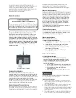
Meter Overview
FCC ID: GIF-RFEPM
FCC CERTIFIED, PART 15, SUBPART C
This device complies with Part 15 of the FCC Rules. Operation
is subject to the following two conditions: (1) this device may not
cause harmful interference, and (2) this device must accept
any interference received, including interference that may
cause undesired operation.
The meter is Badger’s Electronic Preset meter (EPM)
equipped with RF communications allowing
authorization and dispense information. Once a work
order has been set up, the operator simply pulls the
trigger and the authorized amount of fluid for that meter
will dispense. The valve will automatically shut off when
the full amount has been dispensed. A “Top Off” feature
allows additional amounts to be dispensed and tracked
after the valve closes. Upon completion of the dispense
effort, the valve locks prohibiting any unauthorized
dispense to occur.
Overhead view of Keypad
Keypad Installation.
The keypad should be mounted, near a 110 volt
electrical outlet, to a structurally sound wall through the
two holes on the side of the keypads casing. Height on
the wall should be 5 to 6'. Care should be taken to avoid
mounting behind any steel objects (tool storage
cabinets and metal chain linked fences) that may block
the RF communication signal. Care should also be
taken to avoid direct, significant heat sources.
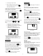
Meter/Keypad Programming
.
The keypad has been wall mounted, paper installed in
the printer, and power supply activated, the unit will go
through certain self-diagnosis. The unit is then ready to


