background image

Reinstalling the Cover Assembly

Badger


Meter recommends that a new O-ring be used after each teardown and reassembly of the cover assembly  To assure a 

tight seal, make sure the O-ring is positioned correctly on the housing and that the O-ring and cover assembly are clean and 

free of dirt or residual traces of old O-ring material  If necessary, use silicone grease to help retain the O-ring and to serve as a 

lubricant in reassembling it to the housing 
Cover bolts should be tightened in a crisscross pattern similar to Turbo head bolts  Torque 2" and 3" cover assembly bolts to  

16…18 ft-lb  Torque the bolts for the 4" and 6" cover assemblies to 35…40 ft-lb 

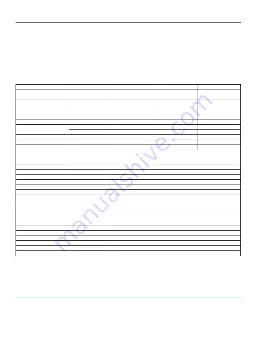
SPECIFICATIONS

Compound Series Model

2" (50 mm) 

3" (80 mm) 

4" (100 mm) 

6" (150 mm) 

Meter Flanges, Class 150

2" elliptical or round

3" round

4" round

6" round

(50 mm)

(80 mm)

(100 mm)

(150 mm)

Typical Operating Range 

0 5…200 gpm

0 5…450 gpm

0 75…1000 gpm

0 75…2000 gpm

(100% ± 1.5%) 

(0 1…45 m

3

/h)

(0 1…102 m

3

/h)

(0 17…227 m

3

/h)

(0 17…454 4 m

3

/h)

Low Flow Registration 
(95% minimum)

0 25 gpm (0 06 m

3

/h)

0 25 gpm (0 06 m

3

/h)

0 375 gpm (0 09 m

3

/h)

0 375 gpm (0 09 m

3

/h)

Maximum Continuous Flow

170 gpm (38 3 m

3

/h)

400 gpm (90 3 m

3

/h)

800 gpm (181 6 m

3

/h)

1500 gpm (340 5 m

3

/h)

Pressure Loss at Maximum 
Continuous Flow

5 4 psi at 170 gpm 

6 0 psi at 400 gpm 

11 0 psi at 800 gpm 

9 3 psi at 1500 gpm 

(0 38 bar at 38 3 m

3

/h)

(0 41 bar at 90 3 m

3

/h)

(0 75 bar at 181 6 m

3

/h)

(0 64 bar at 340 5 m

3

/h)

Crossover Flow Rate, Typical

12 gpm

12 gpm

20 gpm 

30 gpm

Pressure Loss at Crossover

3 5 psi (0 24 bar)

4 0 psi (0 28 bar)

4 0 psi (0 28 bar)

5 0 psi (0 35 bar)

Minimum Crossover Accuracy

97%

97%

97%

95%

Maximum Operating Pressure 

150 psi (10 bar)

Maximum Operating 
Temperature

105° F (41° C)

Test Plug

1-1/2"

2"

Materials

Meter Housing & Cover

Lead-free bronze alloy

Turbo Cast Head

Lead-free bronze alloy

Nose Cone & Straightening Vanes

Thermoplastic

Rotor

Thermoplastic

Rotor Radial Bearings

Lubricated thermoplastic

Rotor Thrust Bearing

Sapphire jewels

Rotor Bearing Pivots

Passivated 316 stainless steel

Calibration Mechanism

Stainless steel & thermoplastic 

Measuring Chamber & Disc

Thermoplastic

High Flow Valve

Stainless steel & thermoplastic 

Magnets

Ceramic

Register Lens

Glass

Register Housing & Cover

Thermoplastic or bronze

Trim

Stainless steel

Drain Plug (3/4") 

Stainless steel or lead-free bronze alloy

Test Plug

Stainless steel or lead-free bronze alloy

Recordall® Compound Series Meter, Lead-Free Bronze Alloy, Sizes 2", 3", 4" & 6"

www.badgermeter.com

Making Water Visible, GALAXY, ORION and Recordall are registered trademarks of Badger Meter, Inc  Other trademarks appearing in this document are the property of their respec-

tive entities  Due to continuous research, product improvements and enhancements, Badger Meter reserves the right to change product or system specifications without notice, 

except to the extent an outstanding contractual obligation exists  © 2016 Badger Meter, Inc  All rights reserved  

Making Water Visible®

The Americas | Badger Meter | 4545 West Brown Deer Rd | PO Box 245036 | Milwaukee, WI 53224-9536 | 800-876-3837 | 414-355-0400 

México | Badger Meter de las Americas, S A  de C V  | Pedro Luis Ogazón N°32 | Esq  Angelina N°24 | Colonia Guadalupe Inn | CP 01050 | México, DF | México | +52-55-5662-0882 

Europe, Middle East and Africa | Badger Meter Europa GmbH | Nurtinger Str 76 | 72639 Neuffen | Germany | +49-7025-9208-0 

Europe, Middle East Branch Office | Badger Meter Europe | PO Box 341442 | Dubai Silicon Oasis, Head Quarter Building, Wing C, Office #C209 | Dubai / UAE | +971-4-371 2503 

Czech Republic | Badger Meter Czech Republic s r o  | Maříkova 2082/26 | 621 00 Brno, Czech Republic | +420-5-41420411 

Slovakia | Badger Meter Slovakia s r o  | Racianska 109/B | 831 02 Bratislava, Slovakia | +421-2-44 63 83 01 

Asia Pacific | Badger Meter | 80 Marine Parade Rd | 21-06 Parkway Parade | Singapore 449269 | +65-63464836 

China | Badger Meter | 7-1202 | 99 Hangzhong Road | Minhang District | Shanghai | China 201101 | +86-21-5763 5412 

Switzerland I Badger Meter Swiss AG I Mittelholzerstrasse 8 I 3006 Bern I Switzerland I +41-31-932 01 11 

Legacy Document Number: RCS-IOM-1

Summary of Contents for Recordall Compound Series

Page 1: ...RCS UM 00076 EN 04 June 2016 Recordall Compound Series Meter Lead Free Bronze Alloy Sizes 2 3 4 6 NSF ANSI Standards 61 and 372 Certified User Manual ...

Page 2: ...Page ii Recordall Compound Series Meter Lead Free Bronze Alloy Sizes 2 3 4 6 June 2016 RCS UM 00076 EN 04 ...

Page 3: ...and Assemblies 12 Removing the High Flow Turbo Meter Head Assembly 12 Removing the Turbo Measuring Element Assembly from the Cover Plate 14 Removing the Magnet Carrier Top Gear Set 14 Removing the Straightening Vanes Nose Cone 14 Removing the Calibration Mechanism 14 Inspecting the Rotor and Bearings 16 Removing the Rear Nose Cone 17 Reinstalling the High Flow Turbo Meter Head Assembly 17 Removing...

Page 4: ...Page iv Recordall Compound Series Meter Lead Free Bronze Alloy Sizes 2 3 4 6 June 2016 RCS UM 00076 EN 04 ...

Page 5: ...ers Product Data Sheet contains information on operating principle meter construction materials tolerances and specifications The Recordall Compound Series Meters Parts List contains part numbers part descriptions and illustrations Safety Information The installation of the Recordall Compound Series meter must comply with all applicable federal state and local rules regulations and codes Failure t...

Page 6: ...es in pipe direction or valving resulting in more accurate registration Contact your Badger Meter representative for information on Recordall Plate Strainers Avoid locating the meter in close quarters Allow sufficient space to permit access for meter reading testing and maintenance Because of the need to test large meters periodically to verify their performance it is recommended that a bypass sys...

Page 7: ...e equal in size to the meter is required upstream of the meter Additional length is required if a sharp contraction or an eccentric reducer rather than a concentric tapered reducer is used Installing the Meter Overall dimensions and laying lengths of each meter size are listed in the Recordall Compound Series Meter Product Data Sheet Review the dimensional requirements choose an installation point...

Page 8: ...ter Figure 4 2 adapter with a 2 round meter Figure 5 4 adapter Figure 6 4 with a 4 meter Description Part Number 2 Elliptical Flange Adapter Kit 64186 001 2 Round Flange Adapter Kit 64186 002 4 Flange Adapter Kit 64186 003 COMPOUND METERS MUST OPERATE IN A COMPLETELY FILLED LINE AT ALL TIMES THE DOWNSTREAM PIPING MUST ALWAYS BE ARRANGED TO PROVIDE SUFFICIENT BACK PRESSURE TO MAINTAIN A FULL LINE A...

Page 9: ...on Now open all applicable service valves Check the flow rate to verify that the flow does not exceed the maximum continuous duty specification The rate of flow can be quickly checked by timing the quantity registered through the meter in one minute Reading the Recordall Registers and Encoder To determine the total reading for meter the totals for both low and high flow must be added together 1 De...

Page 10: ...be added together to determine the total flow through the meter Compare this to that recorded by the test meter or test tank If more than one revolution of the high flow test circle occurs take new readings from the low flow odometer high flow and low flow test circles and add all complete high flow test circle revolutions to this Once again the amount of flow recorded by the high flow and low flo...

Page 11: ...eaning Clean all dirt grease moisture or other foreign material from the exterior of the meter After cleaning rinse thoroughly with water In the event that system pressure has been reduced and the upstream filter or meter is clogged the foreign material must be flushed out To flush the screen open the cleanout plug and purge the foreign material with fresh water from the service line If cleaning t...

Page 12: ...O DO SO CAN LEAD TO THE HEAD BEING EJECTED FROM HOUSING CAUSING PERSONAL INJURY AND OR PROPERTY DAMAGE 1 Loosen each of the High Flow Turbo Head Assembly bolts about 1 1 2 turns Do not completely remove the bolts 2 If the O ring between the High Flow Turbo Head Assembly and the housing is secure and not leaking pry the Measuring Element Assembly loose by inserting a screwdriver blade where the hea...

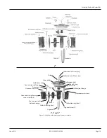
Page 13: ...t bottom bearing Calibration ring rear Rotor Calibration ring front Nose cone setscrew Cage setscrew 1 Cage seal Nose cone straightening vane assembly 2 Calibration shaft seal plug Calibration shaft lock screw O ring Calibration shaft 2 3 and 4 Figure 10 High flow turbo measuring element assemblies Servicing Parts and Assemblies June 2016 RCS UM 00076 EN 04 Page 13 ...

Page 14: ...ain access to them remove the measuring element from the cover Removing the upstream nose cone provides access to the rotor calibration ring and the transmission assembly To remove the nose cone 1 Unscrew the upstream nose cone setscrew For 2 3 and 4 meters slide the calibration linkage into the cage insert stop 2 Take hold of the nose cone straightening vanes and turn them clockwise thereby disen...

Page 15: ...ING 6 Figure 11 Calibration ring linkage assemblies Reassembling the Calibration Mechanism 1 Align the pin on the perimeter of the calibration ring with the arrow tip located on the nose cone assembly see Figure 11 on page 15 2 For 2 3 and 4 sizes install the calibration linkage into the cage with the larger hole to engage the calibration ring tab with the side of chamfered edge of the hole toward...

Page 16: ...ing pins are an integral part of the straightening vane and nose cone assembly Wear or damage would require the replacement of this component Reassembling the Rotor and Bearings 1 Install the rear nose cone to the cage See Removing the Magnet Carrier Top Gear Set on page 14 2 Place the rotor assembly with the worm gear side leading through the cage 3 Place the rotor assembly on the rear rotor bear...

Page 17: ... and out of the bottom bearing then slide shaft downward and diagonally out towards you to remove it from the nose cone cage assembly 7 Holding cage firmly with one hand rotate the nose cone clockwise with other hand then carefully lift it off the cage To reinstall the rear nose cone follow this procedure in reverse See Inspecting the Rotor and Bearings on page 16 for instructions on reassembling ...

Page 18: ...f the Low Flow Cover Assembly bolts about 1 1 2 turns Do not completely remove the bolts 2 If the O ring between the Low Flow Cover Assembly and the housing is secure and not leaking pry the Measuring Element Assembly loose by inserting a screwdriver blade where the head and housing join together BE SURE THAT ANY WATER COMING OUT OF THE METER HEAD DOES NOT SPRAY ONTO ELECTRICAL EQUIPMENT AND CREAT...

Page 19: ... magnet in the meter head is clean Valve Assembly Removing the Valve Assembly With the cover assembly removed the valve assembly is exposed for service 1 Remove the lock pawl see Figure 14 2 Turn the valve assembly counter clockwise to unscrew it from the housing 3 Lift the valve assembly out of the housing Replacing the Valve Assembly If any portion of the valve assembly requires replacement we r...

Page 20: ...stic Rotor Thrust Bearing Sapphire jewels Rotor Bearing Pivots Passivated 316 stainless steel Calibration Mechanism Stainless steel thermoplastic Measuring Chamber Disc Thermoplastic High Flow Valve Stainless steel thermoplastic Magnets Ceramic Register Lens Glass Register Housing Cover Thermoplastic or bronze Trim Stainless steel Drain Plug 3 4 Stainless steel or lead free bronze alloy Test Plug ...

Reviews: