Installation & Operation Manual
05-TUR-UM-00193-EN (September 2012)
Badger Meter
®
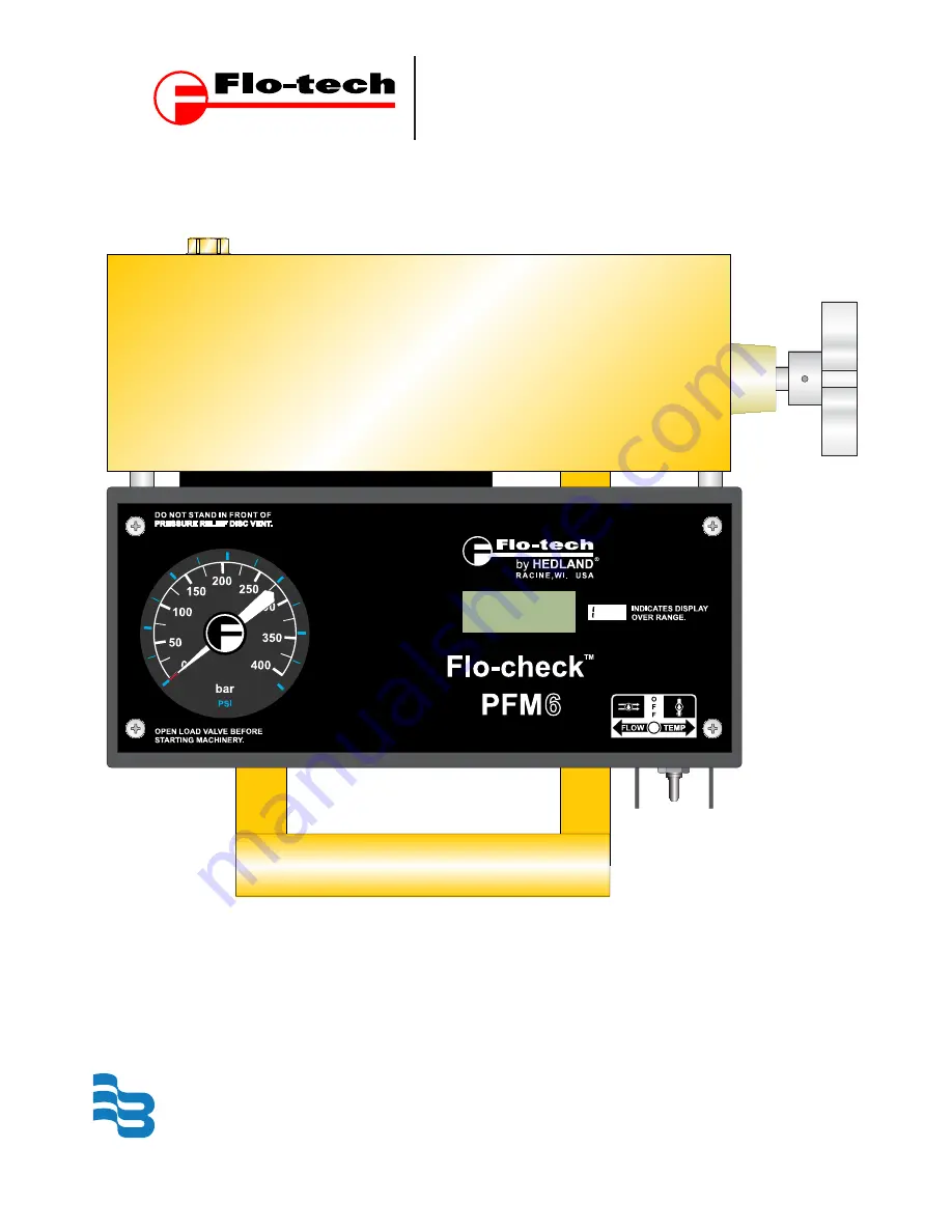
PFM Portable Hydraulic Testers
PFM6, PFM6BD, and PFM8
Page 1: ...Installation Operation Manual 05 TUR UM 00193 EN September 2012 Badger Meter PFM Portable Hydraulic Testers PFM6 PFM6BD and PFM8...
Page 2: ...September 2012 PFM Portable Hydraulic Testers PFM6 PFM6BD and PFM8 Page ii...
Page 3: ...dard Test Conditions 12 Pump Test 13 Tee Test 14 Control Valve Cylinder and Hydraulic Motor Test 16 Relief Valve in Separate Housing 17 Relief Valves 17 MAINTENANCE TROUBLESHOOTING 18 Load Valve 18 Fl...
Page 4: ...PFM8 SLIDE AND MEMBRANE SWITCHES 11 PUMP TEST 13 TEE TEST 14 CONTROL VALVE CYLINDER AND HYDRAULIC MOTOR TEST PFM6BD 16 PFM6 AND PFM8 BURST DISC 19 PFM6BD BURST DISCS 20 BATTERY REPLACEMENT 21 TABLES...
Page 5: ...draulic Tester Features Bi directional testing Low pressure drop Accuracy of 1 of full flow range 3 digit LCD display for flow and temperature Helical tube pressure gauge One toggle switch to control...
Page 6: ...ERS Valve 12L14 steel body with 303 SS stem Spool Sleeve 4340 Alloy steel hardened Straightening Sections 6061 T6 Aluminum Cones 2024 T4 Aluminum Ports SAE Straight thread O ring boss female J1926 1 B...
Page 7: ...GPM PFM6 200 F5076 CE XXX SAE 24 7 199 9 GPM PFM6 15 F5110 CE XXX G 4 56 LPM N A PFM6 30 F5111 CE XXX G 7 5 113 6 LPM PFM6 60 F5112 CE XXX G 1 12 227 LPM PFM6 85 F5113 CE XXX G 1 15 321 LPM PFM6 200 F...
Page 8: ...287 89 249 13 85 6 3 PFM6 60 11 5 3 5 9 8 292 89 249 16 50 7 5 PFM6 85 11 5 3 5 9 8 292 89 249 16 50 7 5 PFM6 200 12 3 4 0 10 3 311 101 262 20 00 9 1 PFM6BD 60 11 3 3 5 10 1 287 89 256 16 50 7 5 PFM6B...
Page 9: ...s illustrating typical test placements for the testers are located in the Test Procedures section OPERATION WARNING Warning All testers are shipped with the loading valve in the closed position The lo...
Page 10: ...n on the PFM6 and PFM6BD models or pressing OFF on the membrane switch of the PFM8 model when the tester is not being used Once the tester has been installed the pressure can be regulated by operation...
Page 11: ...Switches Pressure is displayed as follows PFM6 the gauge indicates pressure at the inlet port PFM6BD the gauge indicates pressure at the inlet port dependent on the direction of flow PFM8 the pressure...
Page 12: ...are designed to measure flow pressure and temperature The PFM8 testers are also designed to measure power The power measurements are derived from the product of flow and pressure When using a PFM6 or...
Page 13: ...WI USA FLOW TEMP O F F TEE PUMP RELIEF VALVE Flo check PFM OUT IN Figure 4 Pump Test 1 Plug the line to the control valve 2 Open the tester loading valve fully to read maximum pump flow at zero pressu...
Page 14: ...OUT port of the tester is connected to the tank Pumps and relief valves can be isolated from the system and checked with the Tee Test TANK OPEN LOAD VALVE BEFORE STARTING MACHINERY INDICATES DISPLAY O...
Page 15: ...m pump pressure to determine pump condition b The pump flow at rated pressure can now be checked against the pump manufacturer s specifications A decrease in flow from zero pressure to maximum pressur...
Page 16: ...K OPEN LOAD VALVE BEFORE STARTING MACHINERY INDICATES DISPLAY OVER RANGE DO NOT STAND IN FRONT OF PRESSURE RELIEF DISK VENT Flo check PFM BD by HEDLAND RACINE WI USA FLOW TEMP O F F CONTROL VALVE TEE...
Page 17: ...onnection a Place the control valve handle in the position where greatest decrease of flow was noted b Close the tester loading valve to achieve the test pressure and record the flow c If the same dec...
Page 18: ...rst Discs and Burst Disc Bodies The burst discs are designed to rupture at a specified pressure The PFM6 and PFM8 testers have a single burst disc that by passes flow around the loading valve when rup...
Page 19: ...is from the sealing surfaces 6 Rotate the tester to face the burst disc port upwards and drop in a new burst disc Make sure it lies flat on the sealing surface entrance Lubricate the O ring on the bur...
Page 20: ...es 6 Rotate the tester to face the burst disc port upwards and drop in a new burst disc Make sure it lies flat on the sealing surface en trance Drop in the support ring and follow it with the second b...
Page 21: ...the cover slowly upward to clear the internal components The batteries are located on the bottom of the case See Figure 9 When installing the new batteries ensure that they are centered in the holder...
Page 22: ...90 100 60 50 40 30 20 10 0 Forward Reverse FLOW GPM FLOW GPM PRESSURE DROP PSI 30 25 20 15 10 5 0 220 200 180 160 140 120 100 60 80 40 20 0 PFM6 200 PFM8 200 PFM6 85 PFM8 85 FLOW GPM PRESSURE DROP PS...
Page 23: ...GPM Hz 60 K K Factor K Hz 60 GPM Time Base TB GPM Hz Flow Rate Related Formulas Valve C Factor Flow Rate GPM Fluid Specific Gravity V P Across Valve PSI Cylinder Velocity 0 3208 Flow Rate GPM Net Cyli...
Page 24: ...aulic Oil 150 32 32 0 28 03 Mobil DTE 24 Hydraulic Oil 200 46 43 2 37 84 Citco Glycol FR 40XD Oil in Water 300 68 65 0 56 94 SAE 20 Crankcase Oil 400 68 100 86 0 75 34 Sunoco Sunvis 41 Hydraulic Oil 5...
Page 25: ...ll returns go to the following address and must include the RGA number on the outside of the box Flo tech 8635 Washington Avenue Racine WI 53406 3738 USA Attn RGA xxx xxxx WASTE AND ELECTRONIC EQUIPME...
Page 26: ...Page 26 September 2012 PFM Portable Hydraulic Testers PFM6 PFM6BD and PFM8 INTENTIONAL BLANK PAGE Materials and specifications subject to change without notice...
Page 27: ...y and shall be void with respect to a Product exposed to conditions other than those detailed in applicable technical literature and Installation and Operation Manuals IOMs or which have been subject...
Page 28: ...3224 9536 800 876 3837 414 355 0400 M xico Badger Meter de las Americas S A de C V Pedro Luis Ogaz n N 32 Esq Angelina N 24 Colonia Guadalupe Inn CP 01050 M xico DF M xico 52 55 5662 0882 Europe Middl...