


SECTION 10B
M1110AY-A Testing HGM300 Monitors Using Gas Verification Kit and PC Software
SCOPE
This Procedure describes the use of gas verification kits with the HGM300 PC software.
MATERIALS USED
•
Reference Gas
•
Variable Flow Regulator
•
HGM300 Refrigerant Monitor
•
HGM300 PC Software
PROCEDURE
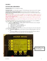
1.
Power up HGM300, the green led on the monitor will blink until the warm-up cycle is complete.
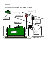
Connect the variable regulator to the reference bottle and connect the tubing to the variable regulator.
2.
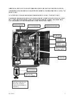
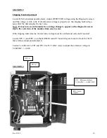
Connect RS232 cable from PC to the HGM300 RS232 connector located in lower left side of the
monitor.
NOTE: For instructions on PC software and setup see instruction manual.
3.
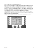
Launch the PC software, when the software is live you should hear a series of beeps while the PC
software reads all the registers of the HGM300.
4.
Verify Rezero mode is set to auto by reading the system parameter list. If not set to auto, select the
“Edit Pulldown Menu” choose the “System” item from the selection list. Change the Rezero mode to
auto, then press the enter key to update the setting. The program should respond with “System Data
Updated”. (On version 1.0 software it is necessary to select the “HGM Pulldown Menu” and then
send the setup in order to confirm the changes)
5.
Select the “HGM Pulldown Menu”, and then choose the get setup item from the menu selection list.
This will update the setup from the HGM300.
6.
Select the “Edit Menu”, and then choose “Zones” from the menu item list. Select Zone by pressing
enter key to modify the parameters for zone1. Change refrigerant to refrigerant type of the reference
bottle. Change the distance parameter to 5 ft, press the enter key then press the ESC key. Wait for PC
software to respond with HGM Zone data updated.
NOTE: Be sure to wait for response from PC
software, selecting another menu before the response is echoed will cause the communications
to timeout. On version 1.0 software it is necessary to select the “HGM pulldown menu” and
then send setup item in order to confirm the changes.
7.
Select “HGM Menu”, then choose “Zone Hold” from the menu item selection list. Select Zone 1 by
pressing the enter key, wait for the PC software to respond with Holding on Zone.
8.
Select “Diagnostic Menu”, and then choose “Sensors” from the menu item list. This will display all
of the diagnostic data for the HGM300. Verify that the unit is not in a purge cycle and take the
pressure reading, write down reading.
Rev 3/2/09
18


