33
33
33
CIS Hail Guards
CIS hail guards are provided to protect the dry coil from hail damage. The CIS hail guards
must be removed before cleaning, to avoid contaminating the dry finned coil surfaces.
Below are the instructions for removal. To re-install the CIS hail guards, reverse the
instructions.
• Lock out and tag out fan and pump motors before performing maintenance on the unit.
• Use appropriate means, complying with applicable safety standards related to working
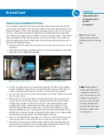
Figure 10.
CIS Hail Guards - Loosen and Remove Hardware from End Covers
on elevated surfaces, to access the top of the unit.
• Loosen and remove hardware from hail guard end covers on the air inlet side of the
unit, and remove covers.
• Slide hail guard bundles out of frame.
NOTICE:
D
o not allow CIS sections
to drag across coil fins, damage to
fins may occur.
Testing the heater when water temperatures are above 45°F (7.2°C):
• Disconnect the heater control panel and tag out the circuit.
• Remove the heater control panel cover.
• Remove the sensor wires connected to terminals T1 and T2 on the combination
temperature/low level control and isolate them.
• Install the 1.5K ohm test resistor supplied with the heater control panel (in bag on outside
of cover) across terminals T1 and T2.
• Install the heater control panel cover.
• Energize the system and listen for the contactor closing.
• After operation, de-energize the circuit, disconnect the heater control panel, and tag out the circuit.
• Remove the resistor and place it back in the storage bag. Check all connections, reconnect
sensor wires per the wiring diagram to terminals T1 and T2, replace the cover, and place the
system back in service.lades for ice formation.
Operation when the sensor probe is encased in ice:
• Disconnect the heater control panel and tag out the circuit.
• Remove the heater control panel cover.
• Install a jumper wire across terminals G1 and G2 on the combination temperature/low level
control circuit board.
• Install the heater control panel cover.
• Energize the system and listen for the contactor closing.
• Operate the system until the ice is melted around the probe.
• After operation, de-energize the circuit, disconnect the heater control panel, and tag out the circuit.
• Remove the jumper, check all connections, replace the cover, and place the system back in service.
NOTICE:
Do not operate the
system unattended or for
extended periods of time
during test mode (resistor
across terminals T1 and T2).
Operation in water
temperatures above 45°F
(7.2°C) could damage the
unit.
NOTICE:
Do not operate the
system unattended or for
extended periods of time
with terminals G1-G2
jumpered. A low liquid level
condition could occur, and
the system will not shut off
which could result in damage
to the heater and unit.
WARNING:
Dangerous voltages
are present in this
equipment. Disconnect
the electrical service of the
source and tag the circuit out
before servicing or replacing
components.
NOTE:
Figure 8 is superseded
by anydrawing supplied with
the panel by the manufacturer.
Figure 9.
Example Wiring Diagram for Stand Alone BAC Heater Control Panel (Refer to Submittal Drawing for Specific Wiring Diagram)


