a
fig. 12
a
fig. 13
a
- 12 -
11. ZIGZAG TIMING • NEEDLE
STOP POSITION
The zigzag timing and the needle stop position when
start/stop switch is pressed are controlled by the
computer system. However, the needle bar position
(upper shaft revolution angle) is detected by the sensor
slit.
Therefore, if the slit is not correct position, the timing and
stop position will be incorrect. Adjust as follows:
1. Remove the front cover.
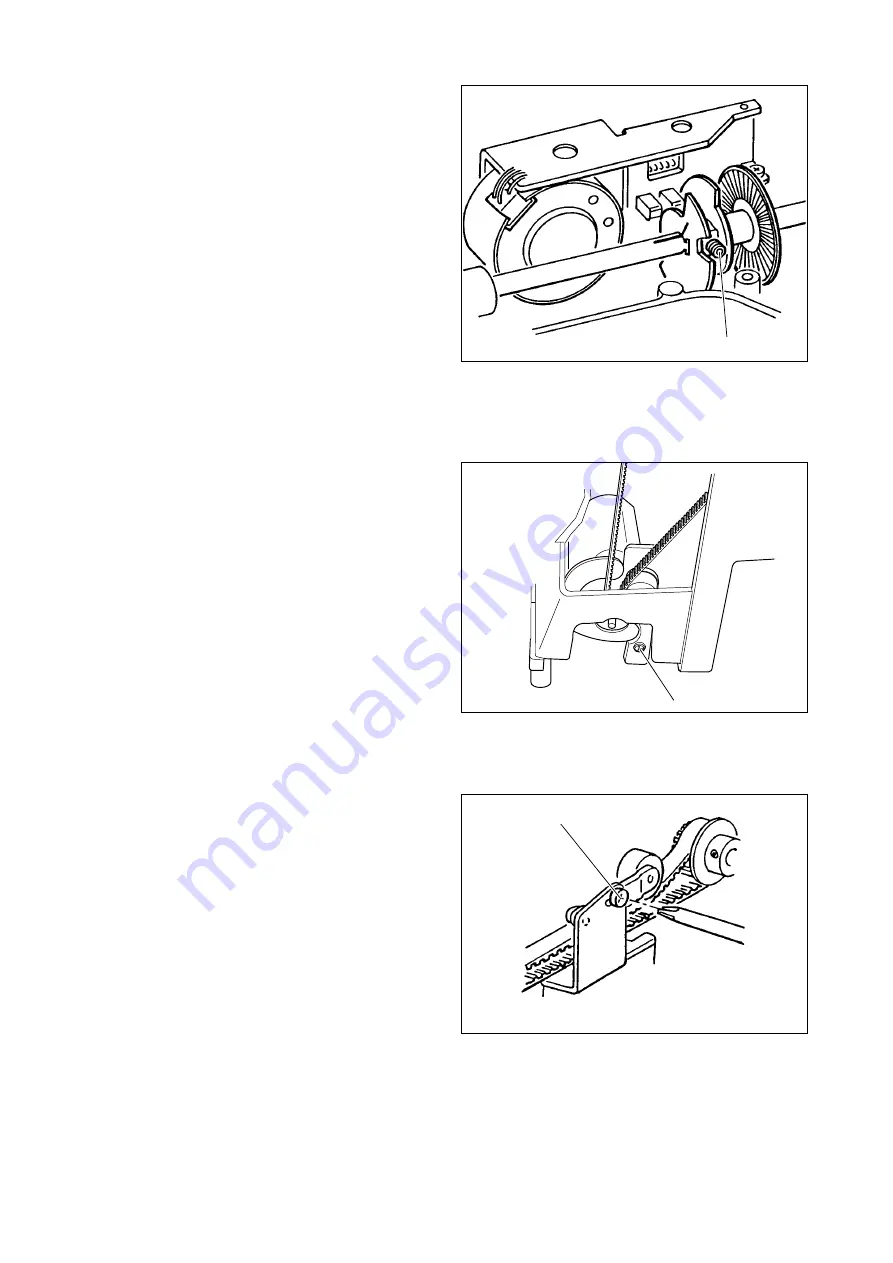
2. Loosen the screw (a) on the timing slit with a hexagon
socket screw key (1.5 mm). (fig. 11)
Align the guide-lines on the upper shaft and left side of
slit.
At this adjustment, do not move the slit side-ways.
3. Tighten the screw (a).
12. MOTOR BELT TENSION
If the motor belt tension is too tight or too loose, machine
will not run smoothly.
Adjust as follows:
1. Remove the front cover.
2. Loosen the screw (a). (fig. 12)
3. Push the pulley towards the belt so that the belt should
have flexibility of 5-6 mm when average pressure is
applied on its side.
4. Tighten the screw (a).
13. TIMING BELT TENSION
If the timing belt is too tight or too loose, the machine will
run heavily or the timing of hook and feed motion will be
changed incorrectly.
Adjust as follows:
1. Remove the front cover.
2. Loosen the screw (a). (fig. 13)
3. Push the pulley towards the belt and tighten screw.
The belt tension should have a flexibility of 4-5 mm
when average pressure is applied to its side.
When you have adjusted the timing belt tension, recheck
the timing of the feed motion (sec. 6) and the timing of the
hook (sec. 3 ) again.
fig. 11 View from lowerside


