b
0
0
1
1
B
F
W
0
1
0
1
O
0
1
- 15 -
b. Condition of switches and
sensors
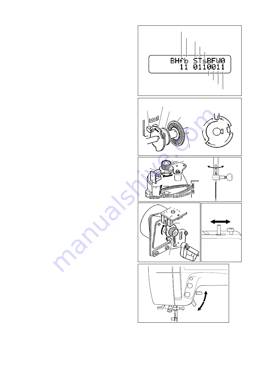
The condition of each switch and sensor is indicated as
follows.
BH f: Buttonhole lever switch -Front
1=Neutral
0=Lever is pushed.
BH b: Buttonhole lever switch -Back
1=Neutral
0=Lever is pulled.
Lower the buttonhole lever and check these switches by
pushing or pulling this lever.
Also, using this mode, you can adjust the buttonhole lever
position. See next page “b-1 Adjustments for buttonhole
lever position”.
S: Stop sensor
1=not intercepted
0=intercepted
T: Timing sensor
1=not intercepted
0=intercepted
s: Speed sensor
1=not intercepted
0=intercepted
These sensors are intercepted by the slit plates on the
main shaft.
Stop sensor = Stop slit, Timing sensor = Timing slit,
Speed sensor = Speed slit
Turn the handwheel and check the response of each
sensor.
B: Sensor of needle bar position
1=not intercepted
0=intercepted (left needle position)
This sensor is intercepted by the lever of gear on the
zigzag pulse motor shaft.
Move the needle bar right or left and check the response
of this sensor.
F: Feed sensor
1=not intercepted
0=intercepted (feed dog is coming
most frontward)
This sensor is intercepted by the lever of gear on the feed
pulse motor shaft.
Remove the base and turn this pulley to check the
response of this sensor.
W: Bobbin winder switch
1=Bobbin winder spindle is in right position
0=Spindle is left position
Move the bobbin winder spindle left or right and check
this switch.
O: Presser foot switch
1=Presser foot is lowered, 0=Presser foot is lifted
Lower or lift the presser foot lifter and check the response
of this switch.
Buttonhole lever switch -Front
Buttonhole lever switch -Back
Stop sensor
Timing sensor
Speed sensor
Sensor of needle bar position
Feed sensor
Bobbin winder switch
Presser foot switch
Stop slit
Timing slit
Speed slit
Sensor
Main shaft
Sensor
Gear
Sensor
Gear


