background image

18

Manual: Baader Planetarium TriBand-SCT

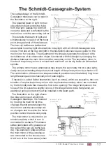
looking in the direction of the Schmidt plate) pushes the main mirror towards the 
Schmidt plate, a right turn pulls the mirror towards the tube back plate.

Now there must inevitably be some space between the outer diameter of the sky 

baffle and the inner diameter of the sleeve; otherwise you could not move the sleeve. 
This minimal difference in diameter (which is sometimes greater and sometimes smal-
ler due to temperature differences) is responsible for the so-called mirror shift. If you 
turn the focus screw back and forth (left and right), the main mirror tilts minimally (due 
to the play in the diameters of the guide sleeve and sky baffle) in its position relative to 
the optical axis. During visual observation, this tilting is noticeable by a slight change 
in the position of the object of observation in the field of view and is not too tragic.

The situation is different in photography: If the position of the telescope tube chan-

ges slowly in the course of the exposure time, 
it can happen that the main mirror suddenly 
changes its position and tilts slightly. This 
results in a change of position of the object of 
observation in the field of view.

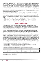
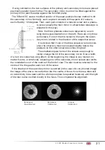
The slight tilting of the main mirror can 

easily be avoided if you "focus correctly". The 
picture on the right is intended to illustrate 
this. "Wrong focus" is when the focus position 
is adjusted by turning the focus screw to the 
right. The mirror is pulled back and the play 
between the sky baffle and the guide sleeve 
is at the bottom left. If the tube now slowly 
moves to a more vertical position due to the 
tracking, the mirror can suddenly slide back a 
little under its own weight.

In the case of "correct focusing", tilting of 

the mirror is impossible. If you turn the focus 
screw to the left (counterclockwise), it pushes 
the main mirror forward. The play between the sleeve and the sky baffle is now at the 
bottom right. The mirror mount is practically clamped onto the Sky Baffle with the 
guide sleeve. This prevents the mirror from tilting.

Attaching Accessories

Caution:

 For mounting accessories, only the three pairs of pan head screws 

1

2

  and 

3

 in the illustration on page 19 may be loosened on the rear tube cell, but 

not the other countersunk screws. For mounting accessories, you may need slightly 
longer screws (8/32 UNC, 1/2 inch). Do not use screws that are too long, as they may 
damage the main mirror. There are one or two screws 

4

 on the front tube cell which 

are used to attach an accessory bar (together with the pair of screws 

2

). We offer 

matching screws under order number 

# 889001 

if no matching screws are included 

with your accessories.

Play

Play

Push

Pull

Focusing 
clockwise

Focusing 
counter-
clockwise

Mirror can 
move

Mirror is 
locked

Summary of Contents for TRIBAND-SCT

Page 1: ...se of a Baader Planetarium TriBand Schmidt Cassegrain These telescopes are made for professional observations of the Sun with large apertures espe cially in combination with H alpha filters and for na...

Page 2: ...for SolarSpectrum H alpha Filter for Photography without Reducer 10 Example Configuration for SolarSpectrum H alpha Filter for Photography with a Reducer 11 Example Configuration for SunDancer TZ3 S T...

Page 3: ...vati on especially with Baader Planetarium and SolarSpectrum H alpha filters or a Baader Herschel prism as well as for narrow band photography similar to using a UHC filter It consists of 1 2 3 4 4 1...

Page 4: ...thread SC thread The Celestron Standard Visual Back for connecting 1 25 accessories is screwed onto it The TriBand 11 also has a 3 3 adapter thread The 2 SC thread allows you to connect heavy accesso...

Page 5: ...e p 20 The TriBand telescopes with their heat shields Avoid setting up the telescope for a long time in such a way that sunlight enters the tube without the telescope pointing directly at the sun The...

Page 6: ...clamp 2956220 if it is equipped with a 2 nose piece Especially with the large SolarSpectrum filters we recommend the sturdy screw connection to avoid tilting On the TriBand telescopes you do not need...

Page 7: ...length included with the TZ 3 to attach SolarSpectrum Filters with T 2 thread Not needed for SolarSpectrum filters with female SC thread 5 SolarSpectrum Filter with female SC thread on both sides Filt...

Page 8: ...2 male only for SolarSpectrum filters with female SC thread included with the SolarSpectrum filters 7 Recommended 3x 1508153 Baader T 2 40 mm Extension Tube 8 2456322 Baader TQC TCR Heavy duty T 2 Qu...

Page 9: ...ngth 1 eye piece is a maximum of about 26 mm that of a 2 eyepiece about 45 mm The achievable field of view is determined both by the diameter of the field stop of the eyepiece and that of the H alpha...

Page 10: ...f the focal length 4 2958244 Baader Reducing Ring 2 i T 2a with 1 5mm optical length included with the TZ 3 to attach SolarSpectrum Filters with T 2 thread Not needed for SolarSpectrum filters with fe...

Page 11: ...er with T 2 threads Filter with SC thread can be attached directly to the telecentric system without 4 6 In addition only for SolarSpectrum Filters which only have a T 2 thread 2958110 Baader T 2 Conv...

Page 12: ...ameras or reducers is done according to the manual of the SunDancer II SolarSpectrum filters do not require an additional block filter when using the TZ3 S or TZ4 S Example Configuration for Baader Fl...

Page 13: ...directly onto the SunDancer unit The 2 Research Grade TZ 3 2459257 has a working distance of 250 mm here we recommend additi onally two pieces 1508153 Baader T 2 40 mm Extension Tube About Magnificat...

Page 14: ...ength If the exit pupil is much smaller than about 0 8 0 7 mm the image contrast will eventually break down Use a double polarising filter or a single circular polarising filter to suppress reflec tio...

Page 15: ...al Barlow lens or telecentric system for focal length adjustment and also the Baader FFC for particularly high magnifications You will find a selection at Baader planetarium com The heat shields are n...

Page 16: ...rom primary mirror baffle tube lock ring 139 mm from 3 in 2 in Reducer Plate 152 mm from 3 in Primary Mirror Baffle Tube Lock Ring Secondary Mirror Obstruction 6 9 cm 8 5 cm 9 5 cm Secondary Mirror Ob...

Page 17: ...The combination of these mirror shapes makes it possible to build relatively long focal length telescopes in mechanically short tube lengths Classical so called Seidel aberrations such as coma which a...

Page 18: ...correctly The picture on the right is intended to illustrate this Wrong focus is when the focus position is adjusted by turning the focus screw to the right The mirror is pulled back and the play bet...

Page 19: ...est 3 Dovetail Bar 470 mm for Celestron 1501615 3 Dovetail Bar 530 mm for Celestron 1501620 These dovetail bars are compatible with the 3 Losmandy standard and can also be installed on top of the tele...

Page 20: ...re concentration Before moving these screws be sure that the system really needs to be collimated and any unsatisfactory view is not caused by seeing effects The following images show a brighter star...

Page 21: ...f one of the three screws is turned clock wise the other two must be loosened slightly before the pressure on the other screws becomes too great The smallest angular turns of the screws are enough to...

Page 22: ...he cloth Occasionally dew condenses on the front lens or Schmidt plate during observation This can be removed with a hairdryer or by pointing the telescope at the ground If moisture condenses inside t...

Page 23: ...nt Do not try to adjust or turn anything by force All mechanical and or electrical movements must be easy to perform 6 It goes without saying that you should not leave your telescope system out in the...

Page 24: ...baader planetarium de www celestron de G M B H Baader Planetarium GmbH All Rights reserved Products or instructions may change without notice or obligation Images and illustrations may differ from th...

Reviews: