background image

I N S - P A F B 1 C _ E N   I n s t r u c t i o n   G u i d e :   F r o n t   B u m p e r    


P a g e  

7 | 12


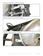
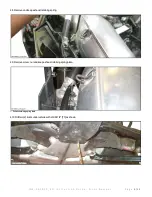
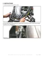
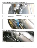
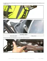
4.11 Remove bumper. 


4.12 Drill two (2) rivets with drill bit 1/4" [T3] as shown. 


Summary of Contents for PAFB-1C

Page 1: ...per use or installation of the product or any modifications made to adapt the product for use in a context other than that for which it was intended voids the warranty and may result in SERIOUS INJURI...

Page 2: ...30 Torx Socket T3 Drill Bit 1 4 T7 Hand Riveter Not Shown T4 Ratchet T8 6 mm Allen Key 3 PARTS ITEM DESCRIPTION PART NUMBER QTY P1 Front Bumper Part 1 FB3A BL 1 P2 Front Bumper Part 2 FB3B BL 1 P3 M6...

Page 3: ...product Make sure you have enough space to work properly Make sure to have the required tools Note Unless differences occur between left hand LH and right hand RH sides the procedures are shown for on...

Page 4: ...A F B 1 C _ E N I n s t r u c t i o n G u i d e F r o n t B u m p e r P a g e 4 12 4 2 Disconnect connectors attached to center panel 4 3 Disengage two 2 locking clip of center panel 4 4 Remove cente...

Page 5: ...u i d e F r o n t B u m p e r P a g e 5 12 4 5 Remove screw nut and keep ground in a visible position for reinstallation 4 6 Remove two 2 screws securing bumper using T27 Torx socket T6 4 7 Remove scr...

Page 6: ...u i d e F r o n t B u m p e r P a g e 6 12 4 8 Remove and keep exhaust retaining spring 4 9 Remove screw nut and keep exhaust retaining spring plate 1 Exhaust retainingspringplate 4 10 Drill two 2 riv...

Page 7: ...I N S P A F B 1 C _ E N I n s t r u c t i o n G u i d e F r o n t B u m p e r P a g e 7 12 4 11 Remove bumper 4 12 Drill two 2 rivets with drill bit 1 4 T3 as shown...

Page 8: ...P a g e 8 12 5 INSTRUCTIONS 5 1 Install front bumper part 1 P1 in position on vehicle 5 2 Locate front bumper part 1 P1 with a M6 X 25 mm hexagonal flanged screw P3 M6 nylon lock nut P5 and exhaust re...

Page 9: ...part 1 P1 with a M6 X 25 mm hexagonal flanged screw P3 M6 nylon lock nut P5 and ground as shown Hand tighten only 1 GroundlocatedonLHside 5 4 Secure front bumper part 1 P1 with two 2 M6 X 25 rounded...

Page 10: ...5 Tighten to specification two 2 M6 nylon lock nut P5 with two 2 10 mm wrench key T2 as shown TIGHTENING TORQUE M6 Nylon Lock Nut P5 10 N m 2 N m 5 6 Secure front bumper part 1 P1 with two 2 3 16 riv...

Page 11: ...11 12 5 8 Install front bumper part 2 P2 with front bumper part 1 P1 using a M6 X 25 mm hexagonal flanged screw P3 and a M6 nylon lock nut P5 as shown TIGHTENING TORQUE M6 nylon lock nut P5 10 N m 2...

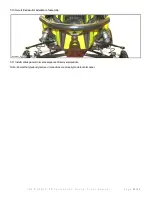
Page 12: ...u i d e F r o n t B u m p e r P a g e 12 12 5 10 Here is final result of installation of assembly 5 11 Install various panels in reverse sequence of removal procedure Note Ensure that previously remov...

Reviews: