background image


15 

6


Menu Tree 


Summary of Contents for 9833B

Page 1: ...1 9830B Series USER MANUAL Model 9832B 9833B High Power Programmable AC Power Sources ...

Page 2: ...lectrical energy available and the voltage impulses that may occur on electrical conductors associated with these category ratings The category rating is a Roman numeral of I II III or IV This rating is also accompanied by a maximum voltage of the circuit to be tested which defines the voltage impulses expected and required insulation clearances These categories are Category I CAT I Measurement in...

Page 3: ...t To minimize shock hazard the instrument chassis and cabinet must be connected to an electrical safety ground This instrument is grounded through the ground conductor of the supplied three conductor AC line power cable The power cable must be plugged into an approved three conductor electrical outlet The power jack and mating plug of the power cable meet IEC safety standards Do not alter or defea...

Page 4: ... are within specifications In direct sunlight This instrument is intended to be used in an indoor pollution degree 2 environment The operating temperature range is 0 C to 40 C and 20 to 80 relative humidity with no condensation allowed Measurements made by this instrument may be outside specifications if the instrument is used in non office type environments Such environments may include rapid tem...

Page 5: ... leads computer interface cables etc discharge all circuits and verify there are no hazardous voltages present on any conductors by measurements with a properly operating voltage sensing device before touching any internal parts Verify the voltage sensing device is working properly before and after making the measurements by testing with known operating voltage sources and test for both DC and AC ...

Page 6: ...instrument to B K Precision for service and repair to ensure that safety and performance features are maintained For continued safe use of the instrument Do not place heavy objects on the instrument Do not obstruct cooling air flow to the instrument Do not place a hot soldering iron on the instrument Do not pull the instrument with the power cord connected probe or connected test lead Do not move ...

Page 7: ...hould not be disposed of as unsorted municipal waste Please utilize your local WEEE collection facilities in the disposition of this product and otherwise observe all applicable requirements CE Declaration of Conformity This instrument meets the requirements of EMC Directive 2014 30 EU Electromagnetic Compatibility Directive and the following standards EMC Directive EN 61326 1 2013 Class A EN 6132...

Page 8: ...t the bottom of the power switch to turn the instrument off Direct current DC Alternating current AC Direct and alternating current DC AC Chassis earth ground symbol Ground terminal Protective earth ground Fuse Symbol CAT I 1000V IEC Measurement Category I Inputs may be connected to mains up to 1000 VAC under Category I overvoltage conditions CAT II 300V IEC Measurement Category II Inputs may be c...

Page 9: ... situation which if not avoided could result in death or serious injury DANGER indicates a hazardous situation which if not avoided will result in death or serious injury NOTICE is used to address practices not related to physical injury Safety instructions or equivalent signs indicate specific safety related instructions or procedures ...

Page 10: ...ix 2 Notations TEXT Denotes a softkey TEXT Denotes a front panel key ...

Page 11: ...rted 10 5 1 Input Power Requirements 10 5 1 1 North American Split Phase Power 10 5 1 2 Fuse 12 5 2 Preliminary Check 12 5 2 1 Power on Procedure 12 5 2 2 Warm up Time 13 5 2 3 Power off Procedure 13 5 3 Sense Lines 13 6 Menu Tree 15 7 Front Panel Operation 16 7 1 Configure Voltage and Frequency Output 16 7 1 1 Setting voltage 16 7 1 2 Setting frequency 16 7 1 3 Setting Voltage 17 7 2 Program Sett...

Page 12: ...er Digital I O Pin Definitions 42 11 3 3 Phase Output Wiring 43 11 4 Phase Control Software 44 11 4 1 Operation Modes Overview 44 11 4 2 Setup and Configuration 46 11 4 3 Three Phase Application Mode 46 11 4 4 Multi Phase Application Mode 49 12 Remote Interface Operation 53 12 1 Interface Connection 53 12 1 1 RS232 53 12 1 2 USBVCP virtual COM 53 12 1 3 USBTMC 54 12 1 4 GPIB 54 12 1 5 LAN Ethernet...

Page 13: ...log input BNC 66 14 Built in Harmonic Wave 68 15 Calibration 83 15 1 AC Voltage Calibration 83 15 1 1 300V range calibration 84 15 1 2 150V range calibration 85 15 1 3 DC Voltage Calibration 85 15 1 4 AC Current Calibration 86 15 1 5 Restore to Factory Default RECALL DATA 87 15 1 6 External Voltage Calibration 88 16 Specifications 91 17 LIMITED THREE YEAR WARRANTY 94 ...

Page 14: ...pulse and list modes Adjustable phase angle control Built in and user definable waveforms Digital I O port for external trigger remote inhibit command completion failure status Analog input for external control Comprehensive protection modes including OVP OCP OTP fan failure key lock 3 1 Package Contents Please inspect the instrument mechanically and electrically upon receiving it Unpack all items...

Page 15: ...2 Note Check that you have the most current User manual This is available for download at www bkprecision com 3 2 Product Dimensions Figure 1 Dimensions ...

Page 16: ...3 3 3 Installation The following diagram shows how to install the optional rack mount kit Figure 2 Rack Mount Kit 1 Step 1 2 3 4 Step 2 5 Step 3 Step 4 6 ...

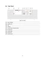
Page 17: ...4 3 4 Front Panel Figure 3 Front Panel Power ON OFF USB disk port VFD Softkeys Function keys Indicator LEDs Number keys Function keys Rotary knob Direction keys ...

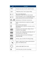
Page 18: ...o a positive or negative value Main function decimal point Secondary function switch from remote control to local control Escape key press to escape the settings menu or cancel the current settings Save key store configurations and settings into the internal memory or a USB disk Recall key recall data from internal storage or external USB disk Enter key press to confirm the settings change Rotary ...

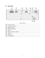
Page 19: ...6 3 5 Rear Panel Figure 4 Rear Panel AC output terminal Remote sense terminal ANALOG connector DIGITAL Input Output LAN port USB port USBVCP or USBTMC GPIB port Ground wire AC input terminal ...

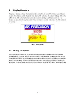
Page 20: ...rument must be returned for service Figure 5 Power on screen 4 1 Display Description At the top right of the screen the remote and output status are displayed Each of the blue softkeys will have a corresponding label to the left These labels will change on each screen to show different options Settings Fields have a black background Settings Fields can be selected by using arrow keys to move to th...

Page 21: ...f x softkey repeatedly Figure 7 Display 1 of 3 Parameter Description Volts rms AC output Vrms setting Volts DC DC output setting Freq Hz Output frequency setting Sync source Select Phase or Immed immediate Phase Ctrl Set Master or Slave for 3 phase operation Phase deg Phase angle setting Table 1 Display 1 of 3 Settings Display 2 of 3 This display shows all 12 power measurements and an output timer...

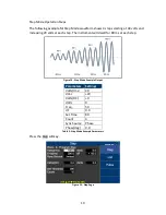
Page 22: ...hows a graphical representation of the settings output measurements and waveforms Figure 9 Display 3 of 3 Press the keys to select and view V voltage waveform or A current waveform Then press the key to change the scale until the complete waveform is visible ...

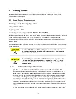
Page 23: ...ire hazard 5 1 1 North American Split Phase Power Split phase is commonly used in North American to provide 208 to 240 Volts This requires two wires that are both hot For example 110 V and 110 V resulting in 220 V across them The included cable may be used in most regions by adding a band of blue electrical tape on each end of the white wire to identify both the black and white with blue band as h...

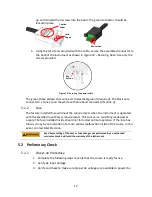
Page 24: ... to the side The black white and green wires should now be clearly visible Use a screwdriver to unscrew and release the white wire only Add a band of blue electrical tape or heat shrink to each end of the white wire 1 Return the white wire into the green connecter and tighten the screw Verify all three wires are secured in the connector 2 Closely inspect each of the wires at the enter point of the...

Page 25: ...e instrument is operated with the specified Input Power requirements This source is a switching mode power supply The fuse installed inside should not fail under normal operation If the fuse has blown it may be an indication of a more serious malfunction inside of the source In this event contact B K Precision Any disassembling of the case or fuse changes not performed by an authorized service tec...

Page 26: ... instrument has completed a full shut down cycle Do not connect multiple power supplies in series or parallel as this may cause damage or a malfunction When the AC input voltage is lower than 190 VAC the source will activate an inner over temperature protector and cut off the output in response to the condition To ensure that the entire test process can be completed smoothly confirm that the input...

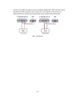
Page 27: ...al sense is the default configuration When remote sense is selected both the sense end L and output end L are connected to the load end L whereas both sense end N and output end N are connected to the load end N Figure 11 Sense Lines ...

Page 28: ...15 6 Menu Tree ...

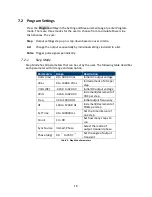
Page 29: ...ER or OK key There are three ways to set the value of output frequency 1 Press number key 6 0 Enter or OK to set Freq Hz 60 2 Use keys to the hundreds digit then press arrow keys or repeatedly until the value reaches 60 Press Enter or OK key to confirm Use keys to select the hundreds digit then rotate the rotary knob until the value reaches 60 Press Enter or OK key or press in on the rotary knob t...

Page 30: ... up Pressing the VOLT key again will switch between VAC and VDC when the coupling mode is AC DC Press the number keys to set the value and press the OK or the Enter key to confirm the change Optionally press the ESC key to cancel the setting change Figure 13 Setting Voltage Vac left Vdc right Vac Vdc ...

Page 31: ...following table describes each parameter with its range and description Parameters Range Description Volts rms 0 to 300 0 Vrms Initial AC output voltage dVac 0 to 300 0 Vrms In decrement of VAC per step Volts DC 424 0 to 424 0 V Initial DC output voltage dVdc 424 0 to 424 0 V Increment decrement of VDC per step Freq 43 to 1200 0 Hz Initial output frequency dF 43 to 1200 0 Hz Increment decrement of...

Page 32: ...easing 20 volts at each step The instrument will dwell for 80 ms at each step Figure 14 Step Mode Example Output Parameters Settings Volts rms 40 dVac 20 Volts DC 0 dVdc 0 Freq 50 dF 0 0 Set Time 80 Count 4 Sync Source Phase Phase deg 0 0 Table 3 Step Mode Example Parameters Press the Step softkey Figure 15 Step Page ...

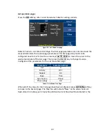
Page 33: ...ode List mode is the only mode with two pages of parameters The first page of parameters is common to all the Second page parameters Only one first page is needed per list The first page Table 4 List Parameters First Page is displayed when the List softkey is pressed and the second page Table 5 List Config Parameters Second Page is displayed when the List Config softkey is pressed Parameters Range...

Page 34: ...ime ms 0 to 999999 Set the time interval for running the specified configuration CYCLE 0 to 999999 Set the period for running the specified configuration Steps 0 to 200 Set the number of steps the specified configuration will be divided into Table 5 List Config Parameters Second Page In the following example 3 new steps will be added to List No 0 Figure 17 List Mode Waveform Parameters Step 1 Step...

Page 35: ... move the cursor to the wanted parameter of the List page Then press the ENTER Key to change its value Configure all the parameters for the List mode first page Parameters Example Settings List 0 Infinity OFF Repeat 02 Base Time Sync Source Phase Phase deg 0 0 When all of the values for the First page have been configured press List Config softkey to move to the Second page The Step No will indica...

Page 36: ...key again to confirm the change Parameters Values Volts rms Start 80 Volts rms End 0 Volts DC Start 0 Volts DC End 0 Freq Hz Start 50 Freq Hz End 50 Time ms 100 Steps 5 Figure List 0 User Step 1 Values After all of the values from have been entered press the Add Step softkey to enter all the changes in to memory and create a new step in List No 0 The Empty Step will change to 99 and Current Step w...

Page 37: ...0 Step 2 Values After all of the values have been entered press the Add Step softkey to enter these changes in to memory and add a new step in List No 0 The page with Empty Step field in yellow will change to 98 and Current Step to 2 Figure 22 Add New Step Parameters Settings Volts rms Start 40 Volts rms End 0 Volts DC Start 0 Volts DC End 0 Freq Hz Start 50 Freq Hz End 50 Time ms 20 Steps 2 Volts...

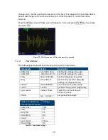
Page 38: ...Parameters Range Description Volts rms 0 to 300 0 Vrms Set the AC voltage of a pulse Volts DC 424 0 to 424 0 V Set the DC voltage of a pulse Freq 43 to 1200 0Hz Set the frequency of a pulse Duty 0 to 100 0 Set the duty cycle for the pulse holding of period time Period 0 to 100000ms Set the pulse to pulse period Count 1 to 99 Set how many pulses to generate Sync Source Immed Phase Select the mode o...

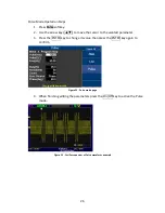
Page 39: ...he cursor to the wanted parameter 3 Press the ENTER key to change its value then press the ENTER key again to confirm Figure 24 Pulse mode page 4 When finishing editing the parameters press the On Off key to active the Pulse mode Figure 25 Oscilloscope view of Pulse waveform example ...

Page 40: ...s Range Description Range 150 V 300 V Select the range of AC output voltage Couple AC DC or AC DC Select the coupling of output voltage Power On State OFF LAST USER OFF When power on the output is OFF LAST When power on the settings will restore to the pre shutdown state USER When power on users need to set the output value and status Volts rms Volts DC Freq Sync Source Inrush Current Measurement ...

Page 41: ...Select to output waveform A or B Waveform A Type SINE SQUA CSIN clipping sine THD0 29 harmonic distortion sine USER0 4 user designed waveform SQUA CSIN clipping sine THD harmonic distortion sine USER user define waveform only for Frequency 100Hz Waveform A Index waveform A clip level 0 29 0 0 to 100 0 When waveform A is THD set index When waveform A is CSIN clipping sine set the clip level Wavefor...

Page 42: ...L or AMP Enable disable the input of the external reference signal OFF Function disable LEVEL Input DC reference voltage 0 to 10 V via the digital IO connector to control output voltage AMP Input reference waveform to BNC connector 6 to 6 V to control output waveform Note If the input frequency is over 1200 Hz the amplitude of output will diminish Remote Inhibit ON or OFF Remote shutdown function ...

Page 43: ... The Configuration Limits page is used to set user defined voltage current and power limits Configurations Range Description Volts rms 0 0 to 306 0 Vrms Set the limit value of AC output voltage Volts Vp 0 0 to 427 0 V Set the limit value of positive DC output voltage Volts Vp 427 0 to 0 0 V Set the limit value of negative DC output voltage A 0 00 to 33 00 A Set the limit value of AC output current...

Page 44: ...he cursor to Volts rms Use keys or Rotary knob to set the value of Volts rms limit and other configurations Then press OK or Enter key to confirm this setting Use keys or Rotary knob to select other configurations NOTE If the output exceeds the limit value the Instrument will stop and the output will display an error message Press the Esc key to close the message window ...

Page 45: ...the wanted configuration Press the ENTER key to change its value and then press the ENTER key again to confirm the changes Configurations Range Description Date YY MM DD Set the date year month day Time HH MM SS Set the time hour minute seconds Brightness 0 to 9 The level of the LCD brightness Beep ON or OFF Enable disable the buzzer Table 13 System Setup Configurations ...

Page 46: ...USBVCP USBTMC GPIB LAN RS232 USBVCP USB Virtual Com Port 19200 N 8 1 USBTMC USB Test and Measurement Class NI VISA Driver is needed GPIB General Purpose Interface Bus LAN Local Area Network RS232 On Digital I O board 19200 N 8 1 GPIB Address 1 to 30 Set the GPIB address IP Mode DHCP Auto Manu STATIC Select how to assign the IP DHCP Auto assigns IP Manu Assign IP address subnet mask and gateway man...

Page 47: ...ors cannot be recovered once it has been cleared Error Code Definition 0x00000080 FW_VerError 0x00000040 SW_EShoutdown 0x00000020 SW_OVAP Software 0x00000010 SW_OPP Software 0x00000008 SW_OVP 0x00000004 SW_OCP 0x00000002 SW_CAN2Error 0x00000001 SW_CAN1Error 0x00018000 AC Input Fail 0x00040000 HW Over Voltage 0x88E00000 HW Over Current 0x33180000 Over Temperature 0x00004000 FAULT_FAN_FAIL 0x0000200...

Page 48: ... to go to the next function page At the System Next screen press Recall Default softkey Press an arrow key to move the cursor to Reset all config Press ENTER key then press the Yes softkey to reset all configurations Figure 34 Recall Default Config 1 2 Field Value Volts rms 50 Volts DC 0 Freq Hz 60 Sync source Phase Phase deg 0 0 Range V 300 Couple AC Power On State Off User On Off State Off User ...

Page 49: ...Inrush Measurement Time ms 0 Inrush Delay Time ms 0 Waveform Select A Waveform A Type Sine Wave A Index 0 Waveform B Type Sine Wave B Index 0 Wave B Index 0 Output Timer Off Timer Setting External Ref Off Remote Inhibit Off Transient Off Table 16 Default Values ...

Page 50: ...nu 10 1 Save Config Press Save Config softkey to store all configurations and settings into the internal memory CFGFile01 cfg to CFGFile09 cfg or into a USB disk CFGFile10 cfg to CFGFile99 cfg Use the number keys to enter the file name Then press OK or ENTER key to confirm or press ESC key to cancel Figure 36 Save Config ...

Page 51: ...oftkey to take a screen shot and store the image to a USB disk SCRFile000 bmp to SCRFile999 bmp Use number keys to enter the file name Then press OK or ENTER key to confirm or press ESC key to cancel Figure 37 Save Screen 10 3 Recall Configuration Figure 38 Recall page ...

Page 52: ...s and settings from internal memory CFGFile01 cfg to CFG09File cfg or from a USB disk CFGFile10 cfg to CFGFile99 cfg Use the number keys to enter the file name Then press OK or ENTER key to confirm or press ESC key to cancel Figure 39 Recall File Selection ...

Page 53: ... mode power on state and inrush current measurement settings can be adjusted in 3 phase mode under the Config 1 menu Under the Config 2 menu external reference and transient settings are disabled in 3 phase mode 11 1 Setup and Configuration The 9830B Series 3 phase operation uses a master slave configuration 3 phase operation requires three identical 9832B or 9833B models One AC source will be set...

Page 54: ...he phase control field on each AC source The options for phase control are Master Slave or Disable The master must be set first Any one of the three connected AC sources can be set to master Use the directional key pad to highlight the phase control field use the soft key to select master and press enter to confirm Figure 11 1 Do not set more than one AC source to Master as this may cause damage o...

Page 55: ...ive DC offset to the AC signal The DC offset can be set from 424 V to 424 V Output of the system is controlled by the master Enabling disabling the output of the master also enables disables the output of slave instruments 11 2 3 Phase Adapter Digital I O Pin Definitions TL983P Pin 9830B Digital I O pin Function 1 23 RX 2 11 TX 3 10 GND 4 19 Remote inhibit 5 4 AC ON 6 16 Fault out 7 Reserved 8 Res...

Page 56: ...43 11 3 3 Phase Output Wiring The 9830B Series supports a Y configuration in 3 phase mode Connect the N terminals on the rear panel together as shown in Figure 11 3 Neutral Line Line Line Neutral ...

Page 57: ... to select Three Phase Application Mode or Multi Phase Application Mode The same setting and range limitations that apply to front panel operation also apply when using the software with the exception of DC offset control Three phase application mode This mode is intended strictly for 3 Phase Operation using three 9832B or 9833B models Setting parameters Voltage Vrms Frequency Hz and Range apply t...

Page 58: ... intended for applications requiring control over more than three phases or when the user wants independent control of each AC source Voltage Vrms and Phase degrees parameters Up to 31 instruments can be connected in multi phase application mode Multi Phase Application Mode Control Panel ...

Page 59: ...cation Setup Press the arrow keys to move the cursor to the wanted configuration Press the ENTER key to change its value and then press the ENTER key again to confirm the changes 11 4 3 Three Phase Application Mode After following the configuration steps you can now connect the 9832B 9833B AC Power Sources to your computer using a standard USB communication cable Each AC Source must be connected t...

Page 60: ...r back on and connect AC Sources to the computer one at a time 2 Click Refresh and the software will automatically search for connected AC sources and assign one master and two slaves Alternatively you can use the dropdown to manually assign master and slave AC sources 3 Click Connect to complete the setup process A successful connection is indicated by the green light as shown Setting Parameters ...

Page 61: ...nitor panel displays live Voltage Vrms Current Arms Power VA and Power W Click Output Off to disable the output of the system Data Logging This software is capable of logging time voltage Vrms current Arms power VA and power W at user defined sampling intervals for each AC Source Data is exported as a CSV file To enable data logging click Setting located in the Output Monitoring panel and the foll...

Page 62: ... appear Check the box under Timer setting to enable the timer Set the desired time in seconds s and click Ok to confirm The timer will start when the output is enabled 11 4 4 Multi Phase Application Mode Communication Setup After following the configuration steps in Section 3 above you can now connect the 9832B 9833B AC Power Sources to your computer using a standard USB communication cable Each A...

Page 63: ...arameters Set Voltage Vrms Phase degrees and Range either 150 Vrms or 300 Vrms for each AC source or the whole multi phase system The phase value of the master must remain at 0 Frequency Hz can only be set for the whole multi phase system Set parameters for each AC source individually by selecting a connected AC source listed under the Setting Parameters table The AC source you are currently setti...

Page 64: ...Current Arms Power VA and Power W Click Output Off to disable the output of the system Data Logging This software is capable of logging time voltage Vrms current Arms power VA and power W at user defined sampling intervals for each AC Source Data is exported as a CSV file To enable data logging click Setting located in the Output Monitoring panel and the following menu will appear ...

Page 65: ...d Output Timer The output timer is used to disable the output after a certain period of time The timer can be set from 1 second to over 277 hours To enable output timer click Setting and the following menu will appear Check the box under Timer setting to enable the timer Set the desired time in seconds s and click Ok to confirm The timer will start when the output is enabled ...

Page 66: ... is not available in 3 phase mode 12 1 2 USBVCP virtual COM The USB port is a virtual COM port which can be used for remote communication See the settings below Settings Value Baud 19200 Data bits 8 Parity None Stop bits 1 Flow control None USBVCP Driver The USBVCP driver for the SiLabs CP210x used in the unit can be downloaded from the following link https bkpmedia s3 amazonaws com downloads soft...

Page 67: ...There are three ways to control the Instrument via LAN interface Web server Telnet connection and Socket connection 12 1 6 Web server There is an embedded web server GUI Graphical User Interface that can access the Instrument via LAN interface using a web browser Using a web browser from a computer connected to the same local area network as the Instrument The GUI provides a simple way to set the ...

Page 68: ...on the page The default admin password is 123456 The web server menu items are described below HOME This page provides general information about the instrument Manufacturer Model Number Serial Number Firmware version Interface USBTMC setting MAC address and IP Address Figure 42 Home Page ...

Page 69: ...omain mDNS host name TCP IP VXI 11 instrument and TCP IP Raw Socket Figure 43 LAN Config Config The Config page provides different settings output voltage range waveform A B output type inrush current Limitations can also be set for R M S voltage Peak voltage output R M S current and output power Figure 44 Source Config ...

Page 70: ...essed here Figure 45 Source Control Log Out The Log Out will exit the web page and go back to login screen The instrument can be connected via LAN Ethernet or Telnet client with a socket port of 5024 Socket connection Socket connection is available for communication via LAN Ethernet interface Users can use this port to open a raw socket connection for sending remote commands The socket port is 502...

Page 71: ...5VDC output reference ground AGND 15 0 8 V 100 mA 3 NONE 4 AC ON OUT When the output of the Instrument is active the voltage level of this pin is high 5V otherwise the voltage level is low 0V reference ground DGND 5 V 0 V 1 mA 5 Reserved Reserved 6 Reserved Reserved 7 Ext_OnOff IN This pin is used with Trigger_in pin17 When the voltage level of this pin is low the Instrument will stop output When ...

Page 72: ...rned from low to high the output will remain off To restart output press Enter or OK key for 2 seconds Refer to the description below for more details 5 V 20 DGND PWR Digital ground 21 Transient OUT When the output status of Instrument has changed this pin will out a 500uS active low pulse Refer to the description below for more details 5 V 0 V 1 mA 22 DGND PWR Digital ground 23 Rx IN RS232 receiv...

Page 73: ...1 2 DC Couple DC couple is selected by setting Configure Config 1 Couple DC The reference voltage is proportional to the source voltage 1 Vdc reference voltage 42 Vac source NOTE Input voltage cannot exceed 10 V to 10 V in DC couple mode This function is not supported when Configure Config 1 Couple AC DC 13 2 Trigger In To activate the Trigger function follow the settings Configure Config 2 Extern...

Page 74: ... Instrument output STOP Falling Edge HIGH Instrument output ON HIGH LOW No change HIGH HIGH No change Falling Edge LOW Instrument output STOP HIGH LOW Instrument output ON Table 19 Control Table Figure 49 Trigger Timing Diagram 13 3 15 VDC This instrument supplies 15 VDC up to 100 mA between pin 2 15VDC and pin 14 AGND Figure 50 15 V supply ...

Page 75: ...on All these outputs are in reference to DGND pins 8 10 18 20 and 22 Figure 51 Output status pin out 13 4 1 SYNC When the output sine wave of the Instrument is about to pass through 0 degrees pin 9 SYNC will send out a 250 uS 12 V to 0 V pulse as shown in the below timing diagram This output Figure 52 Sync Timing Diagram ...

Page 76: ... Module CAN Error 6 SW Over Current Prot 7 SW Over Voltage Prot 8 SW Over Power Limit 9 SW Over Max VA Limit 10 Remote Inhibit ON 13 4 3 Transient When the output status changes pin 21 Transient will send out a 500 uS 5 V to 0 V pulse to synchronize with another external device as shown in the below timing diagram This function is not available in the Program modes To active this function follow t...

Page 77: ...Follow the settings Configure Config 2 Remote_Inhibit ON Figure 54 Remote Inhibit Connection To restore the output back to On first set the voltage level to high 5V then press and hold the ENTER key for 2 seconds Figure 55 Remote Inhibit Timing Diagram 13 6 Tx Rx Pin 11 Tx and pin 23 Rx reference ground is DGND are the send and receive lines of the RS232 interface Open System Comm Select RS232 and...

Page 78: ...l external devices The Instrument uses a opto coupler with an NPN transistor output Event switch ratings Voltage 6 to 60 V maximum Current 50 mA maximum Table 21 Event Switch Power Figure 56 Event Switch Diagram To activate this function connect to pin 13 Event_SW and pin 25 Event_SW and then give switch on off command through SCPI command Command Description TEST DIGI ON TEST DIGI IO SWITCH ON TE...

Page 79: ...The analog input BNC is used to control the output voltage of the instrument with an external signal In this example an Arbitrary waveform generator is connected Figure 57 Configuration 1 page Figure 58 Analog Input Connection ...

Page 80: ...e the cursor to the External Ref then press the ENTER key to change value Select the Amp softkey and press ENTER to save the setting Figure 59 Configuration 2 Amp mode Press ESC to go back to the Setting and Measurement screen Set the arbitrary waveform generator to output 6Vrms 60Hz sine wave then press On Off key to start the output If the AC output voltage range is 150V the output voltage will ...

Page 81: ...68 14 Built in Harmonic Wave THD 00 Harmonic 2 5 7 8 weight 2 07 9 8 15 8 2 16 THD 01 Harmonic 3 7 19 weight 1 5 1 5 2 THD 02 Harmonic 3 5 7 23 31 weight 2 14 2 1 4 1 ...

Page 82: ...69 THD 03 Harmonic 3 5 7 23 25 31 33 weight 2 5 1 9 2 5 1 9 1 1 1 5 1 1 THD 04 Harmonic 3 5 7 9 11 weight 1 1 2 8 1 4 2 3 1 5 ...

Page 83: ...70 THD 05 Harmonic 3 5 7 15 19 weight 1 65 4 2 3 45 1 05 3 THD 06 Harmonic 3 5 7 9 11 15 21 weight 2 2 5 6 2 8 4 6 3 1 4 1 ...

Page 84: ...71 THD 07 Harmonic 3 5 7 11 15 17 weight 4 9 1 6 2 7 1 4 2 1 1 THD 08 Harmonic 3 5 7 11 13 15 17 19 21 23 25 weight 7 35 2 4 4 05 2 1 1 05 3 1 65 1 05 1 05 1 2 1 05 ...

Page 85: ...72 THD 09 Harmonic 3 5 7 9 11 13 15 17 19 21 23 25 weight 9 8 3 2 5 4 1 2 2 8 1 4 4 2 2 1 4 1 4 1 6 1 4 THD 10 Harmonic 3 weight 17 8 ...

Page 86: ...73 THD 11 Harmonic 3 weight 21 3 THD 12 Harmonic 3 weight 24 5 ...

Page 87: ...74 THD 13 Harmonic 2 5 7 8 weight 2 3 9 8 15 8 2 5 THD 14 Harmonic 2 5 7 8 weight 1 15 4 9 7 9 1 25 ...

Page 88: ...75 THD 15 Harmonic 5 7 weight 2 45 3 95 THD 16 Harmonic 3 5 7 9 weight 11 4 05 2 1 3 ...

Page 89: ...76 THD 17 Harmonic 3 5 9 weight 7 17 3 42 0 8 THD 18 Harmonic 3 5 9 weight 8 11 3 48 1 ...

Page 90: ...77 THD 19 Harmonic 3 5 9 weight 9 38 3 44 1 15 THD 20 Harmonic 3 5 7 9 11 weight 2 1 8 1 6 1 23 0 9 ...

Page 91: ...78 THD 21 Harmonic 3 5 7 9 11 13 weight 3 2 75 2 4 2 1 4 0 8 THD 22 Harmonic 3 5 7 9 11 13 weight 4 15 3 8 3 24 2 6 2 1 25 ...

Page 92: ...nic 3 5 7 9 11 13 15 21 23 25 27 29 weight 5 63 5 13 4 42 3 56 2 63 1 68 0 79 1 04 1 27 1 32 1 2 0 95 THD 24 Harmonic 3 5 7 9 11 13 15 21 23 25 27 29 weight 7 28 6 63 5 71 4 61 3 42 2 19 1 04 1 32 1 63 1 69 1 54 1 22 ...

Page 93: ...80 THD 25 Harmonic 5 7 11 13 19 23 25 35 37 weight 3 54 2 68 8 87 7 86 1 04 4 11 4 13 2 61 2 82 THD 26 Harmonic 21 23 25 weight 1 38 5 39 2 29 ...

Page 94: ...9 11 13 15 17 19 21 23 25 27 29 31 33 35 37 39 weight 33 20 14 11 8 5 7 2 6 5 5 4 5 4 3 5 3 2 5 2 2 2 2 2 THD 28 Harmonic 3 5 7 9 11 13 15 17 19 21 23 25 27 29 31 33 35 37 39 weight 33 20 14 11 8 5 7 2 6 5 5 4 5 4 1 1 1 1 1 1 1 1 ...

Page 95: ...82 THD 29 Harmonic 3 5 7 9 11 13 15 weight 33 3 20 13 8 10 8 8 5 7 2 5 5 ...

Page 96: ...t only be performed by authorized technicians or calibration personnel only If you are not authorized do not attempt to calibrate the instrument yourself as you may damage the instrument and void the warranty To enter the calibration procedure access the menu tree System Next Calibration Enter the password 13579 by number keys followed ENTER key to confirm The calibration items are as below VMEAS ...

Page 97: ...rument will output the Low Point voltage Use the number keys to enter the voltage shown on the DMM Press ENTER then the instrument will show OK after Low Point V 4 Press Cal again to start calibration 2 The instrument will output ML Point voltage Use the number keys to enter the voltage shown on the DMM Press ENTER and the instrument will show OK after the ML Point V 5 Press Cal again to start cal...

Page 98: ...calibrate Freq1 through Freq4 Note that the HIGH calibration voltage of 260VAC becomes 140VAC 15 1 3 DC Voltage Calibration Connect the DMM to the output of the instrument Set the DMM to DCV voltage measurement 7 Press System Next Calibration softkeys Enter the password 13579 and select Vdc DC voltage on the calibration menu 1 Press Cal softkey to start calibration The instrument will output Low P...

Page 99: ...e number keys to enter the voltage shown on the DMM Press ENTER and the instrument will show OK after the MH Point V 4 Press Cal softkey to start calibration The instrument will output High Point voltage Use the number keys to enter the voltage shown on the DMM Use the number keys to enter the voltage shown on the DMM Press ENTER and the instrument will show OK after the High Point V The calibrati...

Page 100: ...after the ML Point A 7 Press Cal softkey to start calibration 3 and the instrument will output the MH Point current Divide the voltage shown on the DMM by 3 3Ω shunt and use the number keys to enter the result Press the ENTER key when complete The instrument will show OK after the MH Point A 8 Press Cal Softkey to start calibration 4 and the instrument will output the High Point current Divide the...

Page 101: ...le to supply 10V CAUTION The DC source for external voltage control and the DC source for external voltage calibration should be identical And the external voltage calibration should be completed before using external voltage control function Press System Next External Calibration softkeys in Setting and Measurement screen ...

Page 102: ...xt point softkey to calibrate the second point 5 Supply 0V from the external DC power supply The AD value should be 7900 300 then press the Next point softkey to calibrate the third point 6 Input 9Vdc from the external DC power supply The AD value should be 1000 300 then press the Next point softkey ...

Page 103: ...90 1 The instrument will show Cal End then press ESC to complete the external voltage calibration ...

Page 104: ...igh 32 5 A 100 Hz 25 A 100 Hz 48 75 A 100 Hz 37 5 A 100 Hz Frequency Range Single phase 45 Hz to 1 2 kHz 3 Phase 45 Hz to 600 Hz Phase Range 0 to 359 7 Total 45 to 400 Hz 0 5 Harmonic 400 to 1 KHz 1 Distortion2 1 k to 1 2 kHz 2 Line Regulation3 0 1 Load Regulation3 0 1 resistive load Temperature Coefficient 0 02 per C Crest Factor 45 to 100 Hz 3 25 100 Hz to 1 2 kHz 2 5 Efficiency4 80 typical DC o...

Page 105: ... Peak DC 0 25 3 F S 0 25 2 F S Power 1 of F S for frequency 500 Hz 2 of F S for frequency 500 Hz Frequency 0 5 AC Input Voltage 190 to 250V Frequency 47 to 63 Hz Maximum Power 2500 VA 3800 VA Maximum Current 13 2 A 20 A Power Factor 0 98 typical General Analog BNC Input Input Voltage Range Max 0 to 10 V Input Impedance 200 kΩ Bandwidth 1 2 kHz Storage Memory 10 programs up to 100 steps total list ...

Page 106: ...ord with input connector test report certificate of calibration Optional Accessories Rackmount ears handles RK3U 3 Phase sync adapter TL983P 3 Phase kit TL983P KIT 1 The maximum voltage is limited to 310 Vrms and 438 Vdc 3 Phase mode not supported 2 66 to full range 3 AC mode with sine wave and remote sense enabled 4 150 VAC 150 V range and 300 VAC 300 V range with nominal input AC voltage 5 Analo...

Page 107: ...new instrument via our website www bkprecision com Exclusions This warranty does not apply in the event of misuse or abuse of the product or as a result of unauthorized alterations or repairs The warranty is void if the serial number is altered defaced or removed B K Precision Corp shall not be liable for any consequential damages including without limitation damages resulting from loss of use Som...

Page 108: ...95 22820 Savi Ranch Parkway Yorba Linda CA 92887 www bkprecision com 2020 B K Precision Corp Printed in Taiwan v101320 ...

Reviews: