Remote Transformer
5. Make two connections from remote 12V
transformer to LED source leads (18 gauge
wire) using proper wire connectors (By Others).
See wiring diagram.
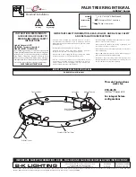
4. Pull low voltage wire to anchor base.
7. Place fixture on anchor base and tighten four
(4) #10-32 stainless steel button head cap
screws using a 1/8” Allen wrench.
Anchor Base Installation
120V
12V
Fixture
COM
Remote
Transformer
COM
120V
12V
Fixture
COM
GROUND
Integral
Transformer
COM
GROUND IN HOUSING
Integral Transformer
6. Pull branch circuit wires neccessary for
installation (By Others) through anchor base.
Anchor base can accomodate up to two (2)
1/2” conduits. Use proper wire connectors
(By Others) to connect transformer primary
leads to branch circuit wires. Connect incoming
ground to ground wire provided in fixture
body. See wiring diagram.
Wiring diagram.
Integral Transformer
Remote Transformer
1. Determine suitable anchors (By Others) to
attach anchor base to architectural surface.
2. Place provided template in final mounting
position according to designed lighting plan.
3. Drill holes into surface for maximum 7/16”
fasteners (By Others) on locations illustrated on
template.
40429 Brickyard Drive • Madera, CA 93636 • USA
559.438.5800 • FAX 559.438.5900
www.bklighting.com • [email protected]
B-K LIGHTING
PROJECT:
TYPE:
IMPORTANT SAFETY INFORMATION LISTED ON REVERSE
READ, FOLLOW, AND SAVE ALL SAFETY AND INSTALLATION INSTRUCTIONS
3167387
ETL LISTED
CONFORMS TO ANSI/UL STANDARD 1838,
CERTIFIED TO CSA STD C22.2 NO.250.7
CSA STD C22.2 TIL B-58A
PS™ /BS™/PSL™/ BSL™
Installation Instructions
TECHNOLOG
with
PRELIMINARY
12-19-11
REFERENCE
NUMBER
INS000891