

Product Overview
Setting Up Your Device
Set Up Hardware
Install/Setup
4
1
2
Set Up Network
3
“I want DHCP” is preselected to set up the network
using dynamic IP addressing. The gateway is set up at
the factory to receive an IP assignment from a DHCP
Server.
1. If a DHCP Server is not available on your network, it
will default to 169.254.102.39.
2. If a DHCP server is not available and the default
address does not work on your PC, change your PC
network settings to IP Address: 169.254.102.1, Subnet
Mask: 255.255.0.0, Default Gateway: 169.254.102.100.
Set Up Serial Port
5
Note: Serial settings are grayed out when VCom
Mode is selected.
1. Change the description of the serial port if
needed.
2. Set the mode to RS-232, RS-422 (4-wire),
RS-485 (2-wire) or RS-485 (4-wire).
3. Set the Baud Rate to control the speed of the
port. Valid rates range between 75 and 230.4k
bits per second.
4. Set Data Bits. Options are from 5 to 8 Data Bits. 8
is most common and is the default.
5. Set Stop Bits. Stop Bits controls the number of
bits for end of character.
6. Parity controls the error checking mode, with
options of: No Parity, Odd, Even, Mark and Space.
7. “Flow Control” options are Hardware or Software or
None. Hardware is used for RS-232 only.
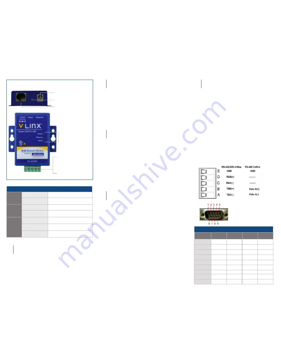
RS-485 DB9 Male Pinout
DB-9M Pin
RS-232
Direction
(RS-232)
RS-422/485
4-wire
RS-485
2-wire
1
DCD
Input
RDA (-)
–
2
RD
Input
RDB (+)
–
3
TC
Output
TDB (+)
Data B (+)
4
DTR
Output
TDA (-)
Data A (-)
5
GND
Output
GND
GND
6
DSR
Input
–
–
7
RTS
Output
–
–
8
CTS
Input
–
–
9
–
–
–
–
Power 10 - 30 VDC
Reset/Mode Switch
Ethernet Port
LEDs
Model VESP211-485
= Removable
Terminal Block
E D C B A
Models VESP211 &
VESP211-232
= RS-232 DB9 Male
1. Port Settings: Four configurations are available:
TCP, UDP, VCOM Mode and Paired Mode.
TCP is the most common choice, and will be briefly
described below.
(Paired Mode uses the same settings as TCP.) Detailed
information about UDP and VCOM Mode may be found
in the user’s manual.
2. TCP Port Settings:
- Choose “TCP”.
- Choose either “server” or “client.”
- Enter the port number on which you want to “wait for
connections.”
- Enter the maximum number of desired connections.
- Specify who is permitted to connect.
Depending on the Mode selected, there may be
advanced functions available. Option is grayed out for
VCom Mode.
1. Connect RJ45 first. DHCP is enabled by default.
2. Power the device.
3. Connect the Serial Device.
RS-232 with DB9: straight-through for DCE device.
Null modem for DTE device.
RS-422/485 with terminal blocks.
1. Use included CD to install Vlinx Serial Server
Manager. If Autorun does not start, go to “My
Computer” and select the CD drive. You will see a Vlinx
VESR icon. Double-click it to launch the installation.
2.
Click “Login”. Password is blank from factory.
No password is necessary to operate the VESR
unit. The Configuration/General page appears.
LEDs
Ready
Blinking
System operating correctly
OFF or Solid ON
Not operating correctly
or not ready
Ethernet
ON
Ethernet port is connected
Blinking
Data is being transmitted
or received
Serial
ON and “Ready”
LED is Blinking
Serial port is available
Blinking
Data is being transmitted
or received
ON but “Ready”
LED is OFF
Device is in Console Mode


