

Product Overview
Install Drivers
Set Dip Switches
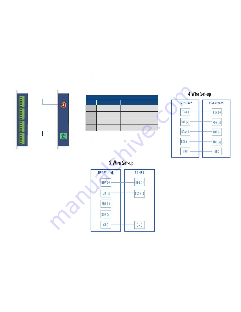
Wire the Converter
1
2
3
Use the included CD to install the converter’s drivers.
Warning: To prevent installation errors, do not
plug in the hardware until you have already
installed the drivers
After connecting the device you can check Device
Manager to learn which Com port number was
assigned (Control Panel/ System/Hardware/Device
Manager/Ports LPT
& COM).
You can re-assign COM numbers by clicking the
Advanced Settings button on the Port Settings
screen.
2-Wire RS-485
o All DIP Switches = ON
Front
Rear
Power
Terminal
Block
USB Port
DIP Switch Position
Switch
OFF
ON
1
TD always enabled
(TD 422)
TD only enabled during data
transission (TD 485)
2
RD always enabled
(ECHO ON)
RD disabled during data trans-
mission (ECHO OFF)
3
4-wire mode
(4-Wire)
2-wire mode (2-Wire)
4
4-wire mode
(4-Wire)
2-wire mode (2-Wire)
OFF=left ON=right
4-Wire RS-422/485
o RS-422 = All DIP Switches OFF
o RS-485 = DIP 1 ON, DIP 2, 4 and 4 OFF
Loopback Test
4
Set the device for RS-485 (4-Wire). Loopback the
TDA(-) to RDA(-) and TDB(+) to RDB(+). Using
Hyper Terminal or similar program, connect to
the appropriate COM port. Set the desired baud
rate. Ensure that Hyper Terminal local echo is
OFF. Transmit data. If the same character string is
returned, the test is good.
Check LEDs
5
When everything is installed and connected the
LEDs will blink to let you know that data traffic is
passing through the converter.


