

Refer to the product user manual for detailed operating instructions.
For more information regarding DTE and DCE connections and the
RS-232 standard in general, visit www.advantech-bb.com
Product Overview
Getting Started
Operation
1
2
Model 232BSS4 provides RS-232 communication to four
devices from one serial port. Each port contains a dedicated
UART and an 8K byte Transmit and Receive Buffer, allowing
each port’s data rate, data format, and protocol to be
configured independently.
Master Port & Slave Ports -
The Master port can send
and receive data from one Slave port while the other Slave
ports continue to buffer data. The Master can also broadcast
the same message to two or more Slave ports at once. The
switch can also be configured to send data automatically to
the Master port from each of the Slave ports when data is
present with an optional preamble identifying the port. It can
also provide two-way communications between the Master
port and one Slave port at a time. LEDs indicate when the
unit is powered up; and which port is selected to send data to
the Master port.
1 Master Port
DB25 Female
(DCE)
232BSS4 SPECIFICATIONS
Powering
10 to 15 VDC / 60 mA
Interface
RS-232 asynchronous
Data Rate
1200 to 115.2 kbps
Flow Control
Hardware (RTS/CTS) or None
MTBF
330865 hours
Temperature
0 to +70 °C
Software
(CD)
Windows 95/98/NT/ME/2000/XP/Vista
4 Slave Ports
DB9 Male (DTE)
Power LED
Port LEDs
The
Master Port
is a DB25 female connector configured
as DCE. This provides a direct connection to an IBM PC
compatible or other DTE device. When connecting the Master
port to a MODEM, the Master port of another 232BSS4, or other
device configured as DCE, a null modem adapter is needed.
Switching and Control
is handled through user-defined
three or four character command strings. These control
sequences are stripped from the data stream, making the switch
transparent to Slave devices.
Cascading
- Multiple 232BSS4 switches can be cascaded to
expand the system. Two units can be used, back-to-back, to
provide automatic connection between devices over a single
data channel.
•
Slave Ports
are DB9 male connectors configured as DTE for
direct connection to a MODEM or other DCE device. When
connecting the Slave ports to a PC compatible or other DTE
device, a null modem adapter is needed.
•
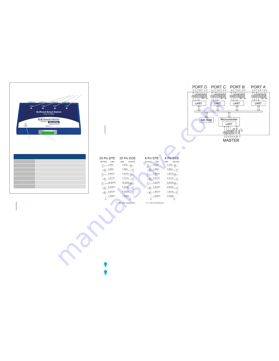
Pinouts
are shown in the block diagram. Only pins 2 and 3
are required for basic operation.
•
Data Format:
7 or 8 Data Bits, even, odd, or no parity
(Master does not support 7 data bits with no parity), 1 Stop Bit
(fixed).
232BSS4. Block Diagram
232BSS4. DTE/DCE Port Diagrams


