B & G B&G User Manual Download Page 52

Commission the System 

 | 51

Ethernet Module Software Version

Software version : 

CA1637C

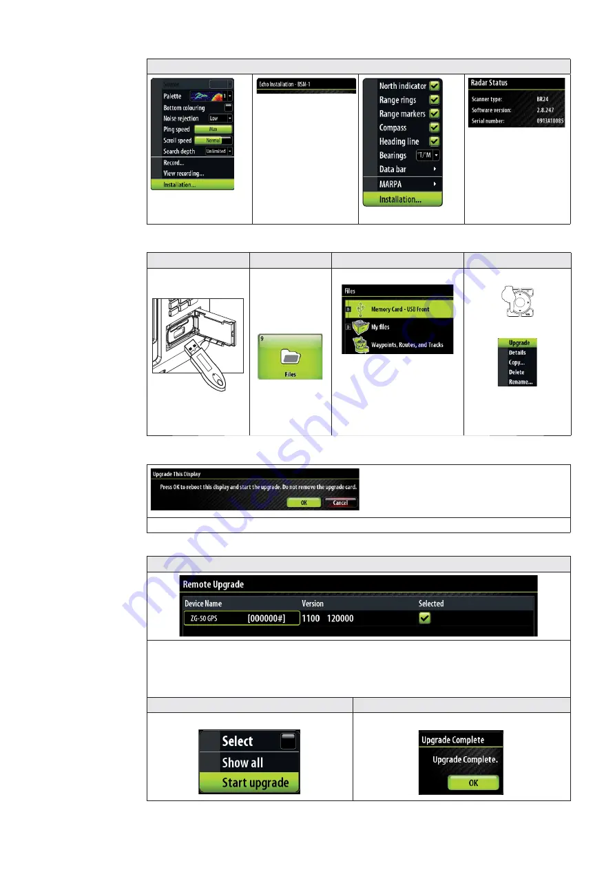
Example below shows upgrading a ZG50 GPS Antenna. Steps 1 - 3 are the same for Zeus 

display upgrades.

Menu Item

Step 1

Step 2

Step 3

Copy upgrade 

fi

 les 

on to a USB Stick

Insert USB Stick 

into front or rear 

USB ports

Press function 

button PAGES
Press 9 or 

navigate to 

fi

 les button

Select Memory card

Select the upgrade 

fi

 le

Press Menu

MENU

9

WIN

Select Upgrade

Additional Zeus Display Upgrade Steps

Do not interrupt power or remove the card, key in “01” when prompted after restart

Step 3 Continued

The Zeus will list devices that can be upgraded by the selected software 

fi

 le. Select the 

unit to be upgraded. (there is only one ZG50 GPS on this network)

Step 4

Step 5

Select start upgrade


Select OK to 

fi

 nish

Step 6. After upgrading a display or Ethernet device please power cycle the entire system

Summary of Contents for B&G

Page 1: ...Installer Manual Zeus Multi function Display English...

Page 2: ...other information relating to the product Documentation may be translated to or has been translated from another language Translation In the event of any conflict between any Translation of the Docume...

Page 3: ...reinstimmung mit den grundlegenden Anforderungen und den anderen relevanten Vorschriften der Richtlinie 1999 5 EG befindet BMWi GR Navico Holding AS Z8 Z12 1999 5 IT Con la presente Navico Holding AS...

Page 4: ...ng Data Interfacing 14 SimNet NMEA 2000 14 Ethernet NETWORK ports 14 NMEA0183 14 B G H Link 14 Data Bridging 15 Wiring Information 16 Typical System 16 Standard Connections 17 NMEA0183 Devices 17 H300...

Page 5: ...ocal Time Time format Date Format 38 Power Control 38 Echosounder Setup 39 Radar setup 40 Data Setup 42 SimNet NMEA2000 setup 42 Source Selection Auto select 42 Source Selection Manual 42 Damping 45 D...

Page 6: ...ional Accessories 55 Compatible BSM 1 Transducers 56 SimNet Accessories 56 Ethernet Cables yellow 57 Ethernet Cables RJ45 57 Repeat Screens 57 Video Cables for Repeat Screens 57 Specifications 58 Supp...

Page 7: ...is an aid to navigation only and is designed to supplement not replace official government charts Only official government charts supplemented by notices to mariners contain the information required f...

Page 8: ...EW OR DRILL PILOT HOLE TO SUIT SELF TAPPING SCREW 5 mm 0 20 192 mm 7 55 192 mm 7 55 265 mm 10 40 PRODUCT OUTLINE 25 mm 1 00 CUTOUT Check dimensions before cutting Power cable 000 00128 001 Z12 Mountin...

Page 9: ...ncels changes and returns to previous menu level 7 Cursor keypad used to move the cursor on the display and to maneuver in the menu system 8 MENU key Used to display the context menu for the active pa...

Page 10: ...te video inputs see Video In section and one RS422 port NMEA0183 TX RX see NMEA0183 Wiring section 3 SimNet Connects Zeus display to a SimNet or NMEA2000 network see SimNet section 4 Video Out Connect...

Page 11: ...00 mm 4 away from the compass at least 300 mm 12 away from any radio transmitter and at least 1 2 m 4 ft away from any antenna Before cutting a hole in a panel make sure that there are no hidden elect...

Page 12: ...dhesive tape Drill pilot holes for the four hole saw 2 cuts and four self tapping screws used to secure the display If using M4 machine screws use a 5 mm 0 20 drill bit A a ed de ea a ou re ut t o ad...

Page 13: ...g angle when bracket mounted Press the ratchet washers into the 1 bracket Loosely screw securing knobs to the 2 Display unit Temporarily mount the display 3 unit in the bracket and make sure the displ...

Page 14: ...bezel Firmly clip the 9 front bezel in place Zeus Bezel Removal A B C Protect the dash area adjacent to the top edge or bottom edge of the display Apply upwards pressure on the bezel A this will crea...

Page 15: ...3 and H Link SimNet NMEA 2000 SimNet is a proprietary CAN bus network for transfer of navigation data such as wind Position AIS etc between all SimNet or NMEA2000 devices on a SimNet NMEA2000 network...

Page 16: ...imNet Network GPS Heading DISPLAY 1 DISPLAY 2 SimNet Network NMEA0183 Listener A B C Example of Data Bridging A In this example a NMEA0183 talker is connected to DISPLAY 1 B The NMEA sentences are bri...

Page 17: ...CPU GFD Displays 20 20 HV Displays Masthead Unit Speed Depth Sensors AIS NAIS 300 GPS Ant VHF Antenna NMEA 2000 Radio ZG50 RI10 Broadband Radar Pilot Processor Halcyon Gyro Stabilised Compass Hydrauli...

Page 18: ...dard Connections NMEA0183 Devices Video Comms NMEA0183 NMEA0183 Device Zeus Display H3000 Zeus Display H3000 H Link USB Deckman Navigation Software Zeus Display H3000 Deckman Navigation Software Video...

Page 19: ...18 Wiring Information WTP3 Zeus Display Serial Interface Video Comms NMEA0183 Deckman Navigation Software WTP3 Can Network Ethernet...

Page 20: ...o radar transmitter or large current carrying cables If cables are shortened lengthened or re terminated seal and protect all wiring connections Do leave room at the back to install and remove cables...

Page 21: ...The yellow Power Control wire can either be an input that will turn on the display when power is applied or an output that turns on other devices when the display is powered on It can be configured a...

Page 22: ...mode 12 24 V DC Red Black Power Control Master Power Control Slave BR24 Radar Yellow Red Black Yellow Red Black Power Control Bus Yellow _ A B C Power Control Master Display A turns on using the powe...

Page 23: ...an ignition switch NO NO Can have more than one on a system YES YES If Power control wire is not connected If a display has its power state controlled by another display or ignition switch it can t b...

Page 24: ...lly in the system i e they can be configured on one display and seen heard and acknowledged from all displays How ever the external alarm siren can be enabled or disabled on individual displays For in...

Page 25: ...nications and access to True Wind Calibration tables H Link LT is available on H3000 Hydra and Hercules CPUs Polar data is not available on H3000 Hydra and H3000 Hercules Processors B G H Link Pro H L...

Page 26: ...EA2000 network by using adapter cables see SimNet cables list SimNet Connector 3 4 5 1 2 Pin Function 1 CAN_H 2 SimNet power 12 V DC 3 SimNet power 4 Shield 5 CAN_L SimNet is a proprietary data networ...

Page 27: ...s of SimNet cable 7 way joiner Use to connect up to 5 devices at one location Wind transducer If using a wind sensor plan to connect this to one end of the backbone as this has a terminator built in P...

Page 28: ...r is required at the end of the backbone _ 12 V DC SimNet backbone SimNet power SimNet terminator A B C E D G H F SimNet drop cable T T T Key Description A SimNet power source Stable 12 V DC only B 5...

Page 29: ...ned by a bayonet type locking collar If more than three network devices need to be connected use the optional network expansion Port For multi station systems it is recommended to use a network expans...

Page 30: ...nnect two or more Zeus displays without an network expansion port However this will mean any display with a device connected by Ethernet will need to be powered on for other Zeus displays to use the d...

Page 31: ...TX TX TX NMEA0183 Talker NMEA0183 Listner Key Pin Color Cable color description Cable Connector A Red Video in port 1 B Green Video in port 2 C 8 Orange RS422 RX 7 Green RS422 RX 6 Yellow RS422 TX 5 B...

Page 32: ...ot distributed to other displays Only one video input can be viewed at a time Video inputs can be cycled Video In Connector VIDEO 1 VIDEO 2 VIDEO IN 1 7 6 5 4 3 2 8 Pin Function 1 Video 1 Ground 2 Vid...

Page 33: ...or Z12 VIDEO OUT DI15 From Z12 only 1024x768 DI10 From Z8 only 800x600 A B MO19 Or third party monitor From Z8 or Z12 scales to resoloution Video Out cable part numbers Optional Key Part Number Descri...

Page 34: ...onnected directly to Zeus or via a Network Expansion Port See Ethernet cables yellow for more cable length options F SimNet Drop Cables The BroadBand Radar and Zeus are connected to the SimNet backbon...

Page 35: ...65 ft E Ethernet cable RJ45 male male Available in 2 5 and 10 m 6 5 16 5 33 ft For cable options see Ethernet Cables RJ45 D HD Radar Processor F Ethernet Adapter cable Yellow 5 pin Male to RJ45 femal...

Page 36: ...le C Ethernet cable yellow 5 pin see Ethernet cables yellow for more cable length options Cable can be connected directly to Zeus or via a Network Expansion Port see Ethernet D 12 or 24 V DC E Transdu...

Page 37: ...when no external equipment is connected you will be asked to run in simulator mode Operating the Menu System In this manual you will see few direct text references to keys menus and menu entries and f...

Page 38: ...rform any manual source set up Set NMEA0183 baud rate and output sentences Settings relevant to displays with NMEA0183 devices attached Set up of SimNet groups for parameters such as dimming and alarm...

Page 39: ...or save Local time Time Offset against GMT from the GPS Default is GMT MENU WIN Highlight Time format PLOT MARK GOTO VESSEL Choose Time format MENU WIN To date format or Save 12 or 24 hour time value...

Page 40: ...e from the paddle wheel to match the actual speed This can be measured either from the GPS speed over ground SOG or by timing the boat over a known distance Water speed calibration should be performed...

Page 41: ...ot be correct if the correct transducer is not selected from the transducer type menu See compatible transducer list Note Other depth sources will have their own calibration Radar setup Basic set up i...

Page 42: ...rejection Low Med or high Default is off HD Pulse Radar Range Offset The timing of the transmit and receive circuits can be adjusted to determine zero range Position the vessel stationary about 150 2...

Page 43: ...ESSEL Choose Auto Select PLOT MARK GOTO VESSEL Start Auto Select PLOT MARK GOTO VESSEL Select OK when finished Source Selection Manual Devices can be selected manually to be the preferred source This...

Page 44: ...ult group would use the input to the Zeus 12 Device Group Source Selection NONE You may prefer one display to receive its position information from the GS10 antenna independently from the rest of the...

Page 45: ...or alarms or displays on the bridge J1 J2 J3 J1 J2 J3 J1 J2 J3 J1 J2 J3 Cockpit Nav Station ZEUS PLOT MARK GO TO VESSEL MENU WIN OUT RANGE IN 1 2 3 6 5 8 9 7PQRS TUV WXYZ MNO JKL ABC DEF GHI 4 0 STBY...

Page 46: ...set to zero Data received from H3000 is already damped Device List Using the Device List Function you can list all of the active SimNet and NMEA2000 devices on the network showing model description a...

Page 47: ...ARK GOTO VESSEL Select Baud Rate PLOT MARK GOTO VESSEL Select OK NMEA 0183 Output Select the desired NMEA0183 sentences to be transmitted see Supported NMEA0183 sentences for more information Uncheck...

Page 48: ...fuel consumption information Fuel used since last fill Fuel used on current trip Fuel used during the season Calibration of the tanks is needed to display accurate fuel levels Vessel Setup AIS Own Ve...

Page 49: ...displays that have had changes made to their settings are also shown Bus State Indicates if SimNet backbone is operating Check power Check termination RX Overflows Overruns greater than 0 could indica...

Page 50: ...s settings such as page layouts and custom instruments can be made at any time and can be stored on the Zeus or transferred to a USB stick or SD Card Creating a System Backup File STEP 1 Press direct...

Page 51: ...es can be performed on the following types of devices from any Zeus display Zeus displays SimNet devices Ethernet devices The same procedure is used to upgrade software on all types of devices Upgrade...

Page 52: ...avigate to files button Select Memory card Select the upgrade file Press Menu MENU 9 WIN Select Upgrade Additional Zeus Display Upgrade Steps Do not interrupt power or remove the card key in 01 when p...

Page 53: ...n to capture Step 3 MOB ABC DEF 1 2 3 JKL GHI MNO 4 5 6 TUV PQRS WXYZ 7 STBY AUTO PWR 8 0 9 Short press on PWR button to capture screen shot File Transfer Step 1 Step 2 Insert a USB Flash drive or SD...

Page 54: ...Drawings 53 Drawings 10 Z8 Dimensions 111 3 mm 4 38 86 5 mm 3 40 285 0 mm 11 22 221 0 mm 8 70 212 0 mm 8 35 315 5 mm 12 40 35 mm 1 38...

Page 55: ...54 Drawings Z12 Dimensions 357 0 mm 14 01 385 mm 15 16 273 0 mm 10 75 266 0 mm 10 47 122 7 mm 4 83 98 mm 3 85 65 mm 2 55 35 mm 1 38...

Page 56: ...e 000 00130 001 Connector caps Documentation wallet 988 0186 01 Installation manual 988 0186 00 Operators manual Zeus Optional Accessories Part Number Description 000 10312 001 B G ZG50 GPS Antenna Br...

Page 57: ...t 000 0106 77 HST DFSBL 50 200 kHz transom mount skimmer depth temp 000 0099 95 TS 1BL Temperature sensor non networked 000 0099 93 XT 12BL 3 65 m 12 ft blue transducer extension cable 000 0099 94 XT...

Page 58: ...t 000 0127 56 Adapter cable Ethernet Yellow male to RJ45 female 2 m 6 5 ft 000 0127 51 Ethernet cable yellow 5 Pin 2 m 6 5 ft 000 0127 29 Ethernet cable yellow 5 Pin 4 5 m 15 ft 000 0127 30 Ethernet c...

Page 59: ...rth up external heading or COG Cartography Embedded Navico Insight HD US Navionics Rest of World Navionics Platinum Plus via SD Card Latitude Limit 83 North 85 South Alarms Position Off Course Waypoin...

Page 60: ...24 VDC Display only 33 6W or 2 8A 12 0 V DC 33 6W or 1 4A 24VDC Supported NMEA0183 Sentences TX RX GPS Receive GGA GLL GSA GSV VTG ZDA Transmit GGA GLL GSA GSV VTG ZDA Navigation Receive RMC Transmit...

Page 61: ...n View 129794 AIS Class A Static and Voyage Related Data 129801 AIS Addressed Safety Related Message 129802 AIS Safety Related Broadcast Message 129808 DSC Call Information 130074 Route and WP Service...

Page 62: ...s 130311 Environmental Parameters 130312 Temperature 130577 Direction Data 61184 Parameter Request Command 130840 Data User Group Configuration 130845 Parameter Handle 130850 Event Command 65287 Confi...

Page 63: ...www bandg com 988 0186 01A...

Reviews: