


The P4 Mainboard Series
Page 12
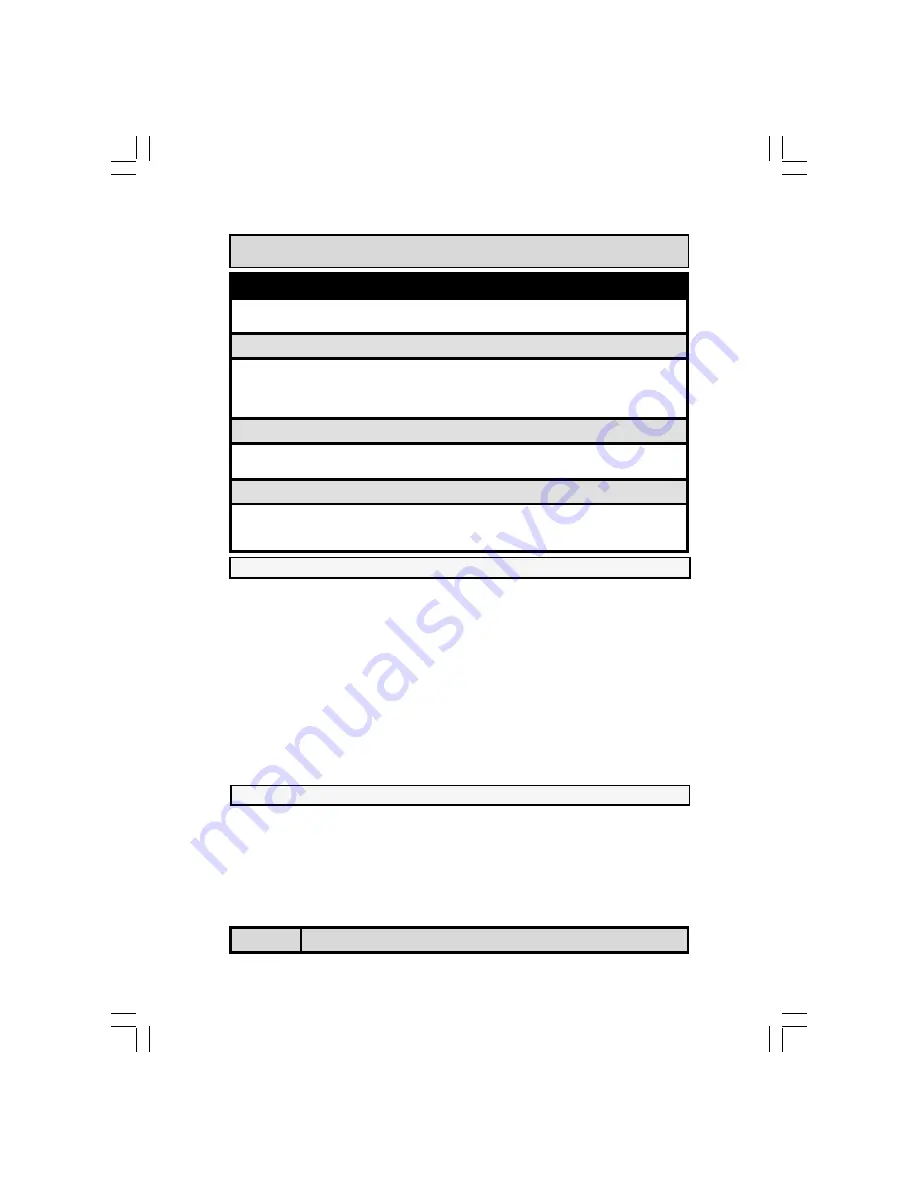
You need to complete the following installation steps before you can use your
PC.
x
Check and Set the Mainboard Settings.
x
Install the Central Processing Unit (CPU).
x
Install the Memory Modules.
x
Install the Expansion Cards.
x
Connect the Ribbon Cables, Panel Wires and the Power Supply.
x
Setup the system BIOS
Before you start installing your mainboard we strongly recom-
mend that you use a grounded anti-static mat. We further rec-
ommend that you attach an anti-static wristband, which is
grounded at the same location as the mat, to your wrist.
! %
Hardware Installation
Installation Checklist (Continued)
CN19
CN35
VGA Port
LAN Port
VGA
(for P4M2-MIB & P4M2-MVB)
LAN
(only for P4M2-MVB)
Speaker and Power LED Connector
PW
SL
HL
RS
Power On/Off and Suspend Switch Connector.
Standby LED Connector
HDD LED Connector
Reset Button Connector
Speaker and Power LED Connector
PWR-LED
SPK
Power LED
Speaker Connector
JP1
JP2
JP4
K/B Power
USB Power
Clear CMOS
Jumpers and Switches
&#'()*%
2.3.1. Installation of the CPU
To install your processor, please complete the following set of instructions
1. Locate a small dot marked on the top of the CPU. This mark indicates
Pin 1 of the CPU.
2. Locate Pin 1 for the Socket on the mainboard.
3.
There is a lever on the side of the socket. First push this lever side-
ways and then lift it to a 90-degree angle.
4.
Insert the CPU into the Socket. Please make sure that Pin 1 for the
CPU is inserted into Pin 1 of the Socket.


