Azbil KFPA User Manual Download Page 42

Azbil Corporation

36

Model 

KFPA

KFTA

 -  Field Mount type Pressure Indicating Controllers

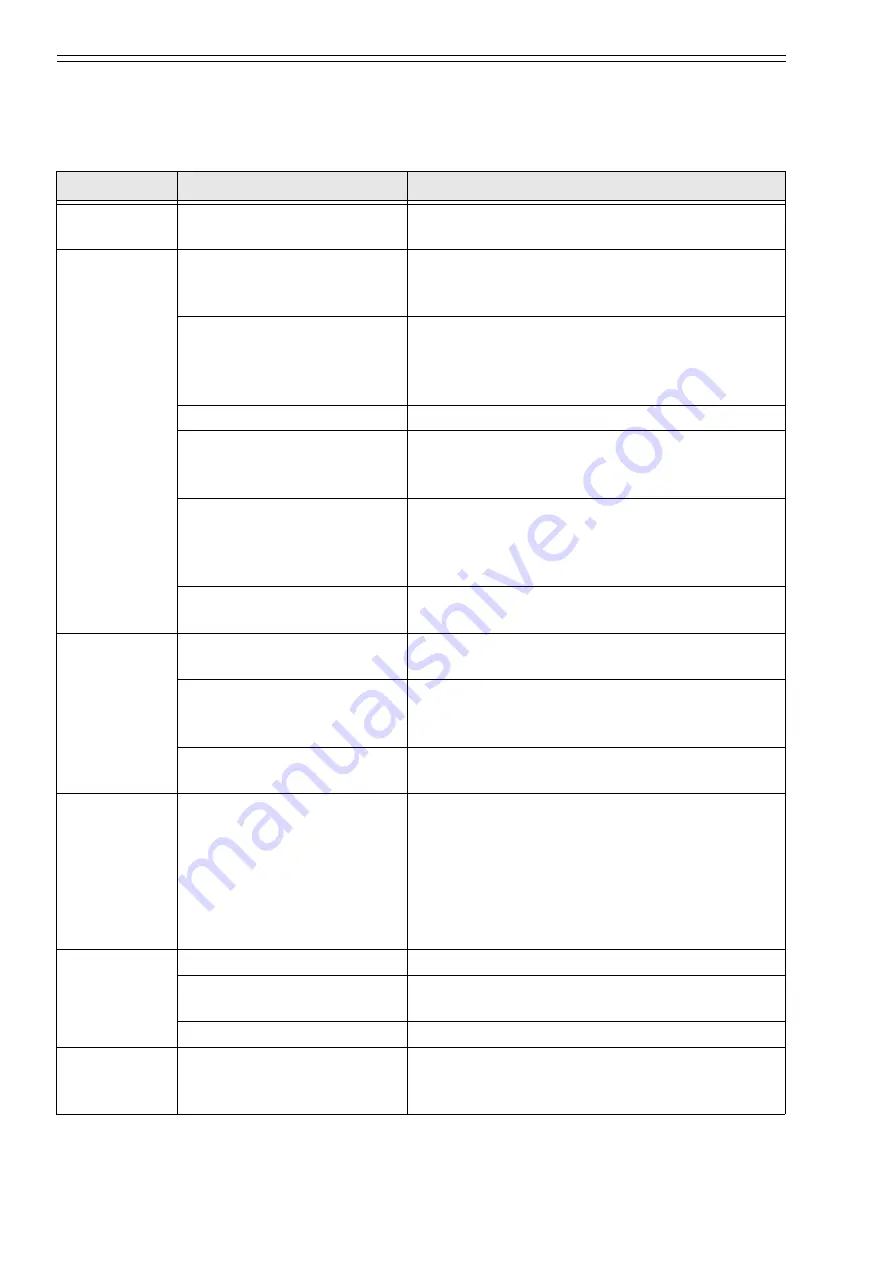
6-5: Troubleshooting

For troubleshooting the instrument, see the following table. For adjustment, refer to the preceding 
chapter.

Symptom

Probable cause

Troubleshooting

Pilot relay 
whines.

Valve sheet is stained.

Remove pilot relay, and clean valve sheet.

Little or no 
control 
pressure is 
delivered.

Supply air pressure is off or 
below 140 kPa {1.4 kgf/cm²}. 
Restriction is clogged.

Provide proper supply pneumatic pressure. 
Remove restriction and clean it.

Restriction is not correctly set. When no transmitter is used, restriction is provided 

with blind plug. Reattach it to correct position.
Correctly set restriction(s) and plug depending on 
whether the instrument has transmitter or not.

Filter is badly stained.

Replace filter

There is leakage in nozzle 
circuit of indicating control 
section.

After making sure that O-rings are properly 
attached, firmly tighten the controller unit and 
restriction.

There is leakage or choking in 
A/M transfer circuit. (When 
A/M transfer switch is 
provided.)

Remove manual control unit and make sure that 
circuit is correct and that O-rings of connecting 
section are properly attached. Then, firmly tighten 
the unit.

There is leakage from pilot 
relay diaphragm.

Remove pilot relay, check diaphragm and, in case 
of leakage, replace diaphragm.

Control 
pneumatic 
pressure is too 
high

Nozzle of indicating control 
section is clogged.

Clean nozzle.

Restriction screw of indicating 
control section is not in firm 
contact with sheet surface.

Tighten so that sheet surface of restriction screw is 
contacted with the manifold.

Valve sheet of pilot relay is 
stained.

Remove pilot relay and clean valve sheet.

Input offset in 
indication is 
large.

Set point pointer or measuring 
pointer is shifted.

Readjust deviation generating mechanism and 
indicating mechanism. (See “5: Calibration and 
adjustment”.)

Control mechanism is not 
properly adjusted. 
(Proportional band is not 
properly balanced.)

Adjust the balancing of control mechanism. (See 
“5: Calibration and adjustment”)

Reset rate is 
abnormal or 
ineffective.

Needle or sheet is damaged.

Use new needle assembly.

Dial attaching screw is noose. Set dial in correct position and fix it firmly with 

screw.

Air is leaking from gasket.

Firmly fix it to the base.

Manual control 
pressure does 
not rise.

Supply pneumatic pressure is 
not applied or below 140 kPa 
{1.4 kgf/cm²}.

Supply proper supply air pressure.

Summary of Contents for KFPA

Page 1: ...Field Mount type Pressure Temperature Indicating Controller Model KFPA KFTA User s Manual OM2 6110 0100...

Page 2: ...ms the implied warranties of merchantability and fitness for a particular purpose and makes no express warranties except as may be stated in its written agreement with and for its customer In no event...

Page 3: ...amage that may have occurred during transportation This equipment was tested under a strict quality control program before shipment If you find any problem in the quality specifications please contact...

Page 4: ...damage it or cause physical injury The glass indicator may break if hit with a tool or other object and cause physical injury This transmitter is heavy During installation please ensure that your foo...

Page 5: ...unit 10 3 Installation 3 1 Air piping 11 3 2 Connection method 11 3 3 Pressure element 12 3 4 Temperature element 13 4 Operation 4 1 Preparations for operation 15 4 2 Pressure control 15 4 2 1 For li...

Page 6: ...30 5 5 1 Pressure element 30 5 5 2 Temperature element 31 6 Maintenance and troubleshooting 6 1 Routine inspection 32 6 2 Controller unit 33 6 3 Pilot relay 34 6 4 Removing the AUTO unit when in manu...

Page 7: ...er in the local mode with the manual setting knob this knob is adjustable either inside the casing or from outside of the casing or in the remote mode with an external pneumatic signal These instrumen...

Page 8: ...in Differential gap 1 to 100 Manual reset 20 to 100 kPa 0 2 to 1 0 kgf cm air pressure setting Batch switch Set pressure 60 to 110 kPa 0 6 to 1 1 kgf cm Air pressure specifications Supply air pressure...

Page 9: ...terial SUS316 Bellows receiving air pressure type is phosphorus bronze Connection Process G1 4 RF1 4 female Pneumatic signal Rc1 4 PT1 4 or NPT1 4 female Measuring range 50 C to 50 C min 0 C to 500 C...

Page 10: ...operation unit Balance bumpless type Manual pressure setting range 10 to 130 kPa 0 1 to 1 3 kgf cm Air consumption 3 min N Air set Pressure regulator valve with filter 40 mm 0 to 200 kPa 0 to 2 kgf c...

Page 11: ...ms the proportional reset and rate actions on the deviation amount in order to produce a pneumatic control output signal 2 2 Descriptions of mechanisms 2 2 1 Deviation generating mechanism The deviati...

Page 12: ...ozzle back pressure is boosted by the pilot relay and delivered as the pneumatic output signal of the controller This output signal is led to the feedback chamber in order to return the flapper to noz...

Page 13: ...control operations a On Off action The nozzle back pressure is directly applied to the pilot relay The control operation is done in an ON OFF mode in response to the open or closed state of the nozzle...

Page 14: ...roduced by a pressure regulator is applied to the reset chamber d Addition of external reset This provision is such that a reset signal as explained in the above item c is applied externally The exter...

Page 15: ...ual controller output pressure When in the manual mode the lever is set in the M position the output pressure of the regulator is led to the reset chamber of the controller unit and at the same time i...

Page 16: ...input signal is indicated as a set point signal on the indicator scale 2 2 5 Batch switch unit When the output has exceeded a preset limit a relay trips so that the reset pressure cannot increase abov...

Page 17: ...nifold of the instrument Note Use of pipe sealing agent may be harmful to pipes If sealing agent is required sparingly apply it to the male connector Output air Connect the pipe for the control valve...

Page 18: ...ion should be paid to the following points 1 Provide a stop valve in the pressure connection tube so as to allow maintenance operation without interrupting the process 2 Provide a cock for drain and a...

Page 19: ...ate the heat sensing section in the center of the pipe and along the fluid flow whenever possible Note Pay attention to the mounting method and the inserted length of the sensing bulb protecting tube...

Page 20: ...ameter d mm Protecting tube diameter D mm Length below screw below flange L mm Specification of screw Flange ratings Min Max 0 50 145 d 12 7 D 17 200 1000 R1 PT1 or R3 4 PT3 4 JIS 10K 25 mm 50 100 50...

Page 21: ...urement See Figure 15 and Figure 16 In case of the clean and non corrosive liquid observe the following instruments for operation of the instrument 1 Open the breed valve while keeping the block valve...

Page 22: ...rials from inside the tube 2 Close the blow down valve Condense the vapor to fill the pressure tap tube and the siphon Open the shutoff valve to start up the operation Figure 16 Piping for measuring d...

Page 23: ...Controllers 17 Figure 18 Piping for measuring vapor pressure Shutoff valve Blow down valve Siphon Stop valve Provide a siphon in the pressure tap line to prevent vapor flow Fully opened the valve duri...

Page 24: ...desired value When the setting knob outside the case is provided setting can be done by turning the knob pressing it toward the door 4 If the check button is pushed with the AUTO MAN switch set in the...

Page 25: ...output to a pressure gauge 2 Perform the following settings and apply a deviation input to saturate the output Proportional band 50 Reset time 0 02 min 3 Decrease the output to the desired value by t...

Page 26: ...ng pin through the adjusting pin hole 4 If there is a gap difference between the ends of the set point pointer and the measuring pointer eliminate the difference by turning the set point pointer adjus...

Page 27: ...at the change in the output pressure becomes less than 0 8 kPa 6 mmHg when the proportional band is changed from 20 to 500 Turn the adjusting pin clockwise if the output increases when the band is cha...

Page 28: ...n 7 Measure the time required by the controller output to change from 53 3 to 60 kPa 400 to 450 mmHg 8 Make sure that the measured time is not longer than 120 60 sec 9 Adjust the position of the reset...

Page 29: ...Pressure Indicating Controllers 23 10 If necessary adjust the position of the rate unit index Figure 22 Rate action calibration 600 300 63 2 t n2 n1 n1 n2 mmHg Rate action fully effected at this poin...

Page 30: ...ointer on the scale 2 Turn fully clockwise the set point dial and set it to the yellow edge line of the INC MEAS DEC OUT scale Then perform a procedure the same as step 1 3 Adjust the deviation link l...

Page 31: ...t type Pressure Indicating Controllers 25 6 Repeat steps of 4 and 5 so that in each of the cases in which the set point dial is set to the white and the yellow line the output will be somewhere within...

Page 32: ...ck link adjusting pin also rotates 360 Make the pin slot horizontal at the side where the link falls when the adjusting pin is turned clockwise 2 Set the set point pointer at 50 Set the differential g...

Page 33: ...ferential gap dial to the 100 position on the right or left side Adjust the feedback link adjusting pin so that the output rises at the setting point to lower the output for once slightly open the fla...

Page 34: ...link and the hole of the span adjusting screw As the connection position is set farther from the center of the element the span becomes larger 3 Linearity adjustment a Check the linearity at the 50 s...

Page 35: ...e becomes 98 4 kPa 738 mmHg The span is decreased as this knob is turned clockwise as viewed from the left side c Repeat the above procedures so that both zero point and span are correctly set Adjustm...

Page 36: ...full close maximum integration time 5 5 1 Pressure element Zero adjustment Turn the adjusting knob on the travel link so that the PV pointer indicates 0 when the element input is set at 0 Span adjustm...

Page 37: ...0 and 100 F S of the temperature range b An accuracy of 1 F S or better is required for the constant temperature bath as calibrated with a standard thermometer c Before starting calibration completely...

Page 38: ...the air supply drain the filter and compressor the air cleaning and dehumidifying equipment and the tank 3 Check for any clogging of the filter and the restriction inside the instrument Replace the cl...

Page 39: ...ws of the controller unit take out the controller unit and clean the nozzle 3 For assembly follow the disassembly procedure in the reverse order Re adjust the control unit after re assembly Confirm th...

Page 40: ...with an appropriate solvent such as petroleum naphtha or chlorosene Do not apply any solvent to the diaphragms To let the solvent to pregnate through the sheet surface push valve system 2 in the direc...

Page 41: ...n 1 Balance the A M output pressure and transfer operation to the M mode 2 Apply a deviation in the direction that the AUTO output pressure decreases Turn the SP knob so that SP becomes smaller than P...

Page 42: ...t circuit is correct and that O rings of connecting section are properly attached Then firmly tighten the unit There is leakage from pilot relay diaphragm Remove pilot relay check diaphragm and in cas...

Page 43: ...lator Zero point change unreasonally when range is changed Parallelism adjustment of transmitter beam is poor Perform parallelism adjustment and calibration Output is unstable or pulsates Air is leaki...

Page 44: ...ual reset With manual reset unit Without rate 2 3 4 1 1 1 With external reset or with manual reset With batch switch General Deviation unit PB setting dial Reset unit Rate unit Cascade rec unit Detect...

Page 45: ......

Page 46: ......

Page 47: ......

Page 48: ...o your use 3 Measures to be taken to secure the required level of the reliability and safety of your Equipment in your use Although azbil is constantly making efforts to improve the quality and reliab...

Page 49: ...argin of your machine or equipment you are required to renew any Azbil Corporation s products every 5 to 10 years unless otherwise specified in specifications or instruction manuals System products fi...

Page 50: ......

Page 51: ...Document Number Document Name OM2 6110 0100 Field mount type pressure temperature indicating controller Model KFPA KFTA User s Manual Date Issued Edited by 15th edition Jan 2020 Azbil Corporation...

Page 52: ......

Reviews: