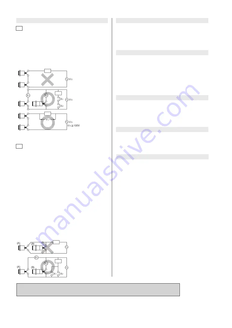
In case of either 100 Vac or 200 Vac, the voltage which is applied
to the load in the ON condition is VL = VS - (output voltage drop
x number of units) (V). Note that the load will not be activated
unless VL is more than the minimum activating voltage of the
load.
When more than 2 units are connected in series and are used in
an AND switching circuit, the maximum number of units is 3.
(Pay attention to the VS value shown in the figure below.)
In principle it is not possible to use more than 2 proximity
switches in parallel as an OR switching circuit. A parallel
connection can be used only if A and B do not operate at the
same time and if it is not necessary to hold the load. However,
consumption current (leakage current) will be multiplied by n (the
number of proximity switches), and recovery failure will occur
more easily.
If A and B operate at the same time and if it is necessary to
retain the load, a parallel connection cannot be used. Under
these conditions, when A is turned ON, the voltage at both ends
of A and B drops to approx. 10V, allowing load current to flow
through A. When a target object approaches B, the switching
element of B cannot be activated because the voltage at both
ends of B is too low. When A is again turned OFF, the voltage
at both ends of A and B increases to the power supply voltage,
and at this point B can be turned ON for the first time.
During this time, since there is a period (approx. 10 ms) when
both A and B are OFF, the load is momentarily reset. In order to
retain the load, use a relay as shown below.
When the proximity switch is connected to a load such as an
electromagnetic switch, lamp or motor that causes inrush current,
use the switch within the rated current, which includes the inrush
current.
After the power is turned ON, it takes at most 80 ms until the
proximity switch is ready for sensing. If the load and the proximity
switch use different power supplies, be sure to turn the proximity
switch ON before turning the load ON.
A minimal current flows as leakage current for operating the
circuits even when the proximity switch is OFF. Keep this in mind
when turning off connected loads.
The minimum bend radius (R) of the cable is 3 times the cable
diameter. Take care not to bend the cable beyond this radius.
Also, do not excessively bend the cable within 30 mm of the cable
lead-in port.
Be sure to connect the proximity switch to the power supply via
the load. If the switch is connected directly to the power supply,
the switch will be damaged. Also, output does not have polarity,
so the load can be connected to either side of the power supply.
However, we recommend connecting the load to the non-
grounded side to prevent short-circuiting of the power supply if a
ground fault caused by damage to the proximity switch occurs.
Load
Load
Load
Load
Load
AC power
supply voltage (Vs)
4.
Cautions for series or parallel connection
5.
Loads that cause inrush current
7.
Operation upon power ON
6.
Connection to power supply and load
8.
Influence of leakage current
9.
Minimum cable bend radius (R)
Series connection (AND switching circuit)
Parallel connection (OR switching circuit)
4.1
4.2
Before use, thoroughly read the “Precautions for use” and “Precautions for handling” in the Technical Guide
on pages
C-107 to C-113 as well as the instruction manual and product specification for this switch.
7
8


