25
© 2013 Axxiom Manufacturing, Inc.
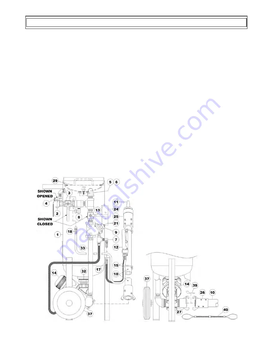
See Figure 5.1 below to help understand the general operation of a Mini abrasive blaster. Do not
attempt to operate the Mini abrasive blaster before reading all sections of this manual and following all
setup procedures. Read sections 5.1 through 5.11 for a detailed explanation of all components of the
Mini abrasive blaster.
Mini abrasive blaster is a
pressurized
system; meaning that the blaster remains pressurized when the
deadman valve (#12) is released.
The Mini abrasive blaster (#1) will pressurize when the blowdown ball valve (#4) is closed and the air
inlet ball valve (#3) is opened. The compressed air enters and is branched off to the blast outlet and to
pressurize the Mini Abrasive Blaster vessel (#1). The air flow into the blast vessel internal piping will
push the pop-up (#5) against the popup gasket (#6). This will seal the abrasive inlet which allows the
air flow to fill and pressurize the abrasive blast vessel (#1).
Blasting starts when the deadman lever (#12) is pressed down. The deadman sends an air signal that
opens both the automatic air valve (#9) and the Thompson Valve® (#14). Compressed air will
pressurize the blast hose (#10) when the automatic air valve (#9) is opened. At the same time, the
Thompson Valve (#14) will open allowing abrasive to fall through and into the blast air stream. The
abrasive flow can be increased or decreased by turning the knob on top of the Thompson Valve.
Blasting stops when the deadman lever (#12) is released. Releasing the deadman will vent the air signal
which will close the automatic air valve (#9) and the Thompson Valve (#14). When the signal air vents,
both valves spring return into their “normally closed” position. The Mini abrasive blaster (#1) remains
pressurized when the automatic air valve and Thompson Valve are closed.
The abrasive blaster (#1) is depressurized by closing the air inlet ball valve (#3) and then opening the
blowdown ball valve (#4) to completely vent the compressed air.
Figure 5.1 –Mini Abrasive Blaster with pneumatic blast controls
5.0 Mini Abrasive Blaster General Operation
Summary of Contents for SCHMIDT
Page 6: ...6 2013 Axxiom Manufacturing Inc...
Page 17: ...17 2013 Axxiom Manufacturing Inc Figure 2 6 Mini Abrasive Blaster Lifting Diagram...
Page 42: ...42 2013 Axxiom Manufacturing Inc THIS PAGE INTENTIONALLY BLANK...
Page 44: ...44 2013 Axxiom Manufacturing Inc 9 1 a Mini Abrasive Blaster w Pneumatic Control System...
Page 45: ...45 2013 Axxiom Manufacturing Inc 9 1 b Pneumatic Control System Parts List 3 5 20 cu ft...
Page 46: ...46 2013 Axxiom Manufacturing Inc 9 2 a Thompson Valve...
Page 47: ...47 2013 Axxiom Manufacturing Inc 9 2 b Thompson Valve II...
Page 48: ...48 2013 Axxiom Manufacturing Inc 9 3 Automatic Air Valve...
Page 49: ...49 2013 Axxiom Manufacturing Inc 9 4 a G2 Pneumatic Deadman...
Page 50: ...50 2013 Axxiom Manufacturing Inc 9 4 b Deadman Valves Pneumatic...


