background image

Synapse Setup 

Software 

Synapse Setup Software can be used to change the settings of Synapse 
modules from a PC, either locally or remotely. The software enables 
communication based on TCP/IP between the Setup PC and Synapse 
frames/modules.  
 
Each Synapse frame is addressed through its rack controller’s unique 
IP address, giving access to each module, its menus and adjustment 
items. The Synapse Setup software has access to data contained within 
the Synapse module and displays it on a GUI. The software has an 
intuitive structure following that of the module that it is controlling.  
 
Having selected the desired Frame and Module from the GUI Synapse 
Network View, select the menu item that you wish to open. Opening 
the menu item gives a complete list of available properties with their 
associated Value. 
 
For example to change a setting e.g. SDI-Format, select SDI-Format 
form the list of settings by ‘double clicking’ to open a dialogue box. 
The dialogue box allows parameters to be changed or set to default 
value. On completion close the dialogue box. 


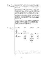
Menu Structure 

Example 

Slot 

Module

 Item  

Parameter 


Setting


S02    Identity  


S01 SFS10

Settings

SDI-

Format 

Auto 


S00 

RRC18 

 Status   Mode   625 


Events 


Ref-Input 


525 


H-Delay 


NOTE: Further information about Front Panel Control and Synapse 
Setup Software can be obtained from the RRC18 and RRC04 
operational manuals. 

Summary of Contents for Synapse ADC20

Page 1: ...____________________________________________ ADC20 4 Channel Analog Audio Input Synapse Add On Card with Delay ...

Page 2: ... Wagenstraat 55 NL 5126 BB Gilze The Netherlands Phone 31 161 850 450 Fax 31 161 850 499 E mail Info axon tv Web www axon tv TECHNICAL MANUAL ADC20 4 Channel Analog Audio Input Synapse Add On Card with Delay ...

Page 3: ... to extremely high or low temperatures NEVER operate this product in an explosive atmosphere Warranty Axon warrants their products according to the warranty policy as described in the general terms That means that Axon Digital Design BV can only warrant the products as long as the serial numbers are not removed Copyright 2001 2006 AXON Digital Design B V Date created 25 09 03 Date last revised 11 ...

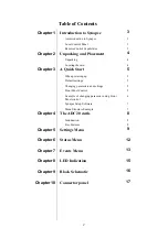
Page 4: ...rt 5 When powering up 5 Default settings 5 Changing parameters and settings 5 Front Panel Control 5 Example of changing parameter using Front Panel control 6 Synapse Setup Software 7 Menu Structure Example 7 Chapter 4 The ADC20 cards 8 Introduction 8 Key Features 8 Chapter 5 Settings Menu 9 Chapter 6 Status Menu 12 Chapter 7 Events Menu 13 Chapter 8 LED Indication 15 Chapter 9 Block Schematic 16 C...

Page 5: ...cal control panel is also used to back up and restore card settings Please refer to the RRC18 RRS18 RRC10 and RRC04 RRS04 manuals for a detailed description of the local control panel the way to set up remote control over IP and for frame related settings and status information Remote Control Capabilities The remote control options are explained in the rack controller RRC18 RRS18 RRC10 RRC04 RRS04...

Page 6: ...t premature failure from components mounted on the board Locating the card The Synapse card can be placed vertically in an SFR18 frame or horizontally in an SFR04 frame Locate the two guide slots to be used slide in the mounted circuit board and push it firmly to locate the connectors Correct insertion of card is essential as a card that is not located properly may show valid indicators but does n...

Page 7: ...anel controls or the Synapse Set Up Software can be used to change settings An overview of the settings can be found in chapter 5 6 and 7 of this manual Front Panel Control Front Panel Display and Cursor Settings are displayed and changed as follows Use the cursor arrows on the front panel to select the menu and parameter to be displayed and or changed Press To go forward through the menu structur...

Page 8: ... to indicate that the SFS10 Settings menu item SDI Format has been selected and shows that it current setting is Auto Pressing the selects the settings item shown in this example SDI Format Pressing or will change to a different setting eg Mode H Delay The display changes to indicate that the SFS10 Edit Setting menu item SDI Format has been selected To edit the setting of the menu item press or Al...

Page 9: ...trolling Having selected the desired Frame and Module from the GUI Synapse Network View select the menu item that you wish to open Opening the menu item gives a complete list of available properties with their associated Value For example to change a setting e g SDI Format select SDI Format form the list of settings by double clicking to open a dialogue box The dialogue box allows parameters to be...

Page 10: ...mbedding function are ASV08 ASV10 ASV20 ASC10 SFS11 21 SEB10 and ADL24 Key Features The Key features of the ADC20 are as follows Performance The ADC20 has high quality 24bit D A converters that are capable of sampling up to 192kHz Levels To maintain maximum performance and optimum noise levels Axon have given the input section of this card a selectable analog gain stage that ensures the A D conver...

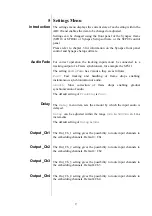
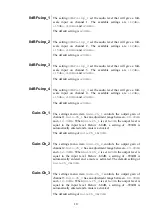
Page 11: ...me drops enabling instantaneous synchronization of audio Smooth Slow correction of frame drops enabling gradual synchronization of audio The default setting of Tracking is Fast Delay The Delay menu item sets the amount by which the input audio is delayed Delay can be adjusted within the range 0ms to 5200ms in 1 ms increments The default setting of Delay is 0ms Output_Ch1 The Out_Ch_1 setting gives...

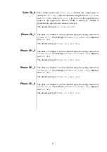
Page 12: ... item Gain Ch_1 controls the output gain of channel 1 Gain Ch_1 has an adjustment range between 60 00dB and 12 00dB When Gain Ch_1 is set to 0dB the output level is equal to the input level Below 60dB a setting of 999dB is automatically entered and a mute is activated The default setting of Gain Ch_1 is 0dB Gain Ch_2 The settings menu item Gain Ch_2 controls the output gain of channel 2 Gain Ch_2 ...

Page 13: ...e Ch_1 are 0 deg degrees and 180 deg The default setting of Phase Ch_1 is 0 deg Phase Ch _2 The phase of channel 2 can be adjusted using the setting menu item Phase Ch_2 The settings of Phase Ch_2 are 0 deg degrees and 180 deg The default setting of Phase Ch_2 is 0 deg Phase Ch _3 The phase of channel 3 can be adjusted using the setting menu item Phase Ch_3 The settings of Phase Ch_3 are 0 deg deg...

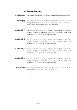
Page 14: ...vailable Audio Ch_2 The status item Audio Ch_2 indicates the condition of the audio signal at the input of channel 2 Audio Ch_2 indicates if the input signal is OK Clipped or NA not available Audio Ch_3 The status item Audio Ch_3 indicates the condition of the audio signal at the input of channel 3 Audio Ch_3 indicates if the input signal is OK Clipped or NA not available Audio Ch_4 The status ite...

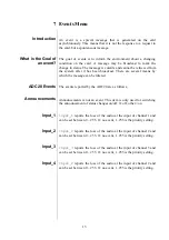
Page 15: ...s reported by the ADC20 are as follows Announcements Announcements is not an event This item is only used for switching the announcement of status changes on off 0 off other on Input_1 Input_1 reports the loss of the audio at the input of channel 1 and can be set between 0 255 0 no event 1 255 is the priority setting Input_2 Input_2 reports the loss of the audio at the input of channel 2 and can b...

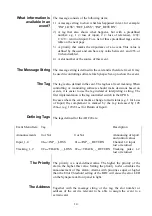
Page 16: ...er to use the tag instead of interpreting a string The first implementation is the tag controlled switch in the GPI16 In cases where the event marks a change to fault status e g 1 for Loss of Input the complement is marked by the tag increased by 128 80hex e g 129 81hex for Return of Input Defining Tags The tags defined for the ADC20 are Event Menu Item Tag Description Announcements 0 or NA 0 or N...

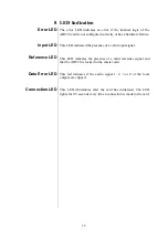
Page 17: ...resence of a valid input signal Reference LED This LED indicates the presence of a valid reference signal and that the ADC20 is locked to the master card Data Error LED This led indicates if the audio signal 1 2 3 or 4 of the local outputs are clipped Connection LED This LED illuminates after the card has initialised The LED lights for 0 5 seconds every time a connection is made to the card ...

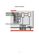
Page 18: ... BUS Rack controller Audio in outputs To from Synapse bus 1 2 3 4 ANALOG AUDIO 1 ANALOG AUDIO 2 ANALOG AUDIO 3 ANALOG AUDIO 4 A D A D A D A D I2S FORMAT Delay offset tracking Gain Phase processing μP 1 Ch 1 Ch 1 Ch 1 Ch 4 1 4 1 4 1 4 1 TRACKING ...

Page 19: ...17 10 Connector Panel The ADC20 can be used with the following backplanes BPL04 BPL05 and BPL05D BPL04 BPL05 BPL05D ...

Page 20: ...18 TRACKING Not Used 4 3 ADC20 1 1 ANALOG AUDIO IN 3 4 2 2 SEE TABEL NEXT PAGE FOR CONNECTIONS J7 J8 J9 J5 J6 J3 J4 J1 J2 J2 J1 ...

Page 21: ..._input_1 positive 2 Analog_input_1 negatieve 1 GND 14 Analog_input_2 positive 16 Analog_input_2 negatieve 15 GND 3 Analog_input_3 positive 5 Analog_input_3 negatieve 4 GND 17 Analog_input_4 positive 19 Analog_input_4 negatieve 18 GND 6 Unused inputs and outputs must be terminated with the correct impedance ...

Reviews: