INITIAL ASSEMBLY
23
Remove the four M5 caphead bolts using a
4mm allen key as shown in figures A & B and
remove the splash guard.
Fig A
Fig B
WARNING
!
When mounting the Mill to the Lathe, we strongly advise you get
the assistance of another person because of the weight of the
machine.
Step 1
Splash guard
Summary of Contents for SIEG C4
Page 2: ......
Page 3: ......
Page 5: ...5 ...
Page 8: ...4 THE CARRIAGE SADDLE 8 ...
Page 11: ...A G H B C D E F Oil LATHE MAINTENANCE OIL LUBRICATION POINTS 11 ...
Page 12: ...12 ...
Page 13: ...13 ...
Page 14: ...14 ...
Page 15: ...15 ...
Page 16: ...16 ...
Page 17: ...17 IV ...
Page 18: ...18 ...
Page 19: ...19 NOTES ...
Page 20: ...600857 Mill Attachment for the C4 Lathe User Manual W H I T E AXMINSTER W 2007 ...
Page 34: ...34 MAINTENANCE OILING POINTS Oil Top of draw bar cover removed for clarity OIL ...
Page 36: ...PARTS BREAKDOWN FOR THE MILL 36 ...
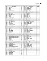
Page 37: ...PARTS LIST FOR THE MILL 37 ...
Page 38: ...38 PARTS LIST FOR THE MILL ...
Page 39: ...39 PARTS LIST FOR THE MILL ...
Page 40: ...40 NOTES ...
Page 41: ...41 NOTES ...


