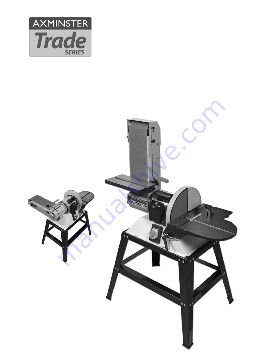
BDS-612 Belt & Disc Sander
Code 505091
Linisher angled at 90˚ (degrees)
Page 1: ...BDS 612 Belt Disc Sander Code 505091 Linisher angled at 90 degrees...
Page 2: ...symbols below advise that you follow the correct safety procedures when using this machine Fully read manual and safety instructions before use Eye protection should be worn Ear protection should be...
Page 3: ...E 1 No Linisher Cust Iron Table F 1 No Linisher Small Table G 1 No Ball Bearing Assembly H 1 No Linisher Sanding Belt I Bag Containing 1 No M8x30mm Bolt Washer J 4 No M8x20mm Hex Bolts K 6 No M6x10mm...
Page 4: ...L M Leg Stand Assembly Quantity Item Part Bag Containing 4 No Rubber Feet R 36 No Coach Bolts 5 16 S 36 No Shake Proof Nuts 5 16 T 4 No Leg Brackets U 2 No Middle Support Brackets Long V 2 No Middle S...
Page 5: ...r sander and it s various components if you do not wish to retain the packaging please dispose of it responsibly especially any polystyrene most of the remaining packaging is biodegradable Keep this I...
Page 6: ...is intended primarily for inside workshop usage Always mount the machine on a flat level stable surface There are several methods of achieving this bolting the machine directly to a good solid workbe...
Page 7: ...ny description if you are tired your attention is wandering or you are being subjected to distraction A deep graze a lost fingertip or worse is not worth it DO NOT use the machine within the designate...
Page 8: ...Model BDS 612 Code 505091 Rating Trade Power 0 93kW 230V 1ph Belt Speed 730m min Belt Size 152 x 1220mm Diameter of Disc 305mm Table Size Belt 305mm x 150mm Table Size Disc 400 x 225mm Dust Extraction...
Page 9: ...figs 06 07 Step 6 Locate the four rubber feet R place a foot to the end of one the legs U lineup the slotted groove in the foot using a high faced mallet lightly tap in place see fig 08 Repeat for th...
Page 10: ...is heavy we advise you seek help to assemble the unit Fig 11 Step 2 Lower the machined cutout in the linisher C over the drive roller lineup the pre drilled holes in the linisher with the four thread...
Page 11: ...the two M6 large star knobs O Position the guard cover D over the lower section of the linisher and lineup the pre drilled holes see fig 21 Screw two M6 screws Fig 21 Fig 20 Fig 18 Fig 19 M in the low...
Page 12: ...he linisher mounting plate and secure with the two M6 screws L see fig 26 Step 8 Locate the cast iron table F and the M8x30mm bolt and washer J slot the machined hole in the table s bracket over the p...
Page 13: ...g Lever 5 Motor 6 Abrasive Disc 7 Disc Guard 8 Mitre Fence B No Description Part 9 Cast Iron DiscTable 10 Stand Assembly UVW 11 Rubber Feet R 12 Table Clamping Handle 13 NVR Switch Assembly 14 Linishe...
Page 14: ...traction output Disc extraction output Linisher belt tracking knob Motor REST button Mitre fence assembly Belt sanding table pointer and scale Pointer Clamping knob Scale NVR Switch assembly Disc sand...
Page 15: ...the table brackets see fig 32 place a rule up against the sanding disc and adjust the table until there is a 1 6mm clearance between the table and the disc see fig 33 Step 3 Replace the disc guard as...
Page 16: ...orrect see fig 40 Fig 40 Tracking the Belt NOTE1 All directions are given from the view point of the operator standing behind the drive drum end looking down the length of the machine The tracking con...
Page 17: ...essure works adversely to the cutting process further it will accelerate the rate of clogging of the abrasive surfaces rendering the machine less efficient WARNING WEAR EYE AND EAR PROTECTION WARNING...
Page 18: ...e table and place safely aside see fig 43 Sanding Disc Fig 45 Step 4 Locate the supplied spanner C and using the 10mm end remove the two nuts on either side of the extraction housing see fig 45 Fig 46...
Page 19: ...ree locking knobs O and N from the side of the linisher guards and place safely aside open the guard s access doors see fig 50 Fig 50 I Step 3 Remove the linisher s sanding belt I Inspect the new belt...
Page 20: ...nd repair motor Motor does not reach full power 1 Incorrect power wiring 2 Overloaded 1 Replace with the correct size of power wiring 2 Reduce load Motor overheating 1 Motor voltage is different 2 Mot...
Page 21: ...Parts Breakdown List 21 BDS 612 Exploded diagram...
Page 22: ...4 505091 14 Cast iron table of platen 1 15 505091 15 Tilting turning of platen 1 16 505091 16 Platen packing 1 17 505091 17 Drive roller 1 18 505091 18 Idler roller 1 19 505091 19 Idler roller shaft 1...
Page 23: ...1 47 Hex head screw M8x12 6 48 Spring washer M8 6 49 Hex head screw M8 x 25 4 50 Washer M8x18 5 51 Nut M8 7 52 Hex head screw M8x16 2 53 Hex bolt M8x15 1 54 Hex bolt M8x18 3 55 Hex bolt M8x20 4 56 Hex...
Page 24: ...ord 1 81 950697 Switch 1 82 505091 82 Sprain release 6W 4S 3 83 505091 83 Connector 1 84 505091 84 Ball bear packing 1 85 505091 85 Key 6 x 6 x50 1 86 505091 86 Pointer 1 87 Set Screw M5x10 2 88 Open...
Page 25: ...ion Specification Qty 1 505091 STAND 1 Leg 618x702mm 4 2 505091 STAND 2 Middle support long 671 x44 5x 1 6 2 3 505091 STAND 3 Middle support short 466 x44 5x 1 6 2 505474 STAND NUT AND BOLT PACK COMPL...
Page 26: ...Wiring Diagram 26...
Page 27: ...Notes 27...
Page 28: ...cycling centre and place into the appropriate recycling bin Do not dispose of electric tools together with household waste material In observance of European Directive 2002 96 EC on waste electrical a...