Axminster 700103 Original Instructions Manual Download Page 27


24 


4.9   Blade  Selection 

The chart below is a basic starting point for choosing blade type based on teeth per inch (TPI) for 
variable tooth pitch blades and for standard raker type bimetal blades/HSS blades. However, for 
exact specifications of bandsaw blades, contact the blade manufacturer. 

Here are some general rules of thumb with respect to bandsaw blade use. 

    At least three teeth must contact the metal at any phase of the cut. Otherwise, the teeth can 

load up with metal, fracture, and break off. If the TPI is too high, the teeth can load up with material 
and overheat, damaging the blade. 

    For a faster but rougher cut, use a blade with a lower TPI and a higher feed rate. 

    For a slower but smoother cut, use a blade with more TPI and a lower feed rate. 


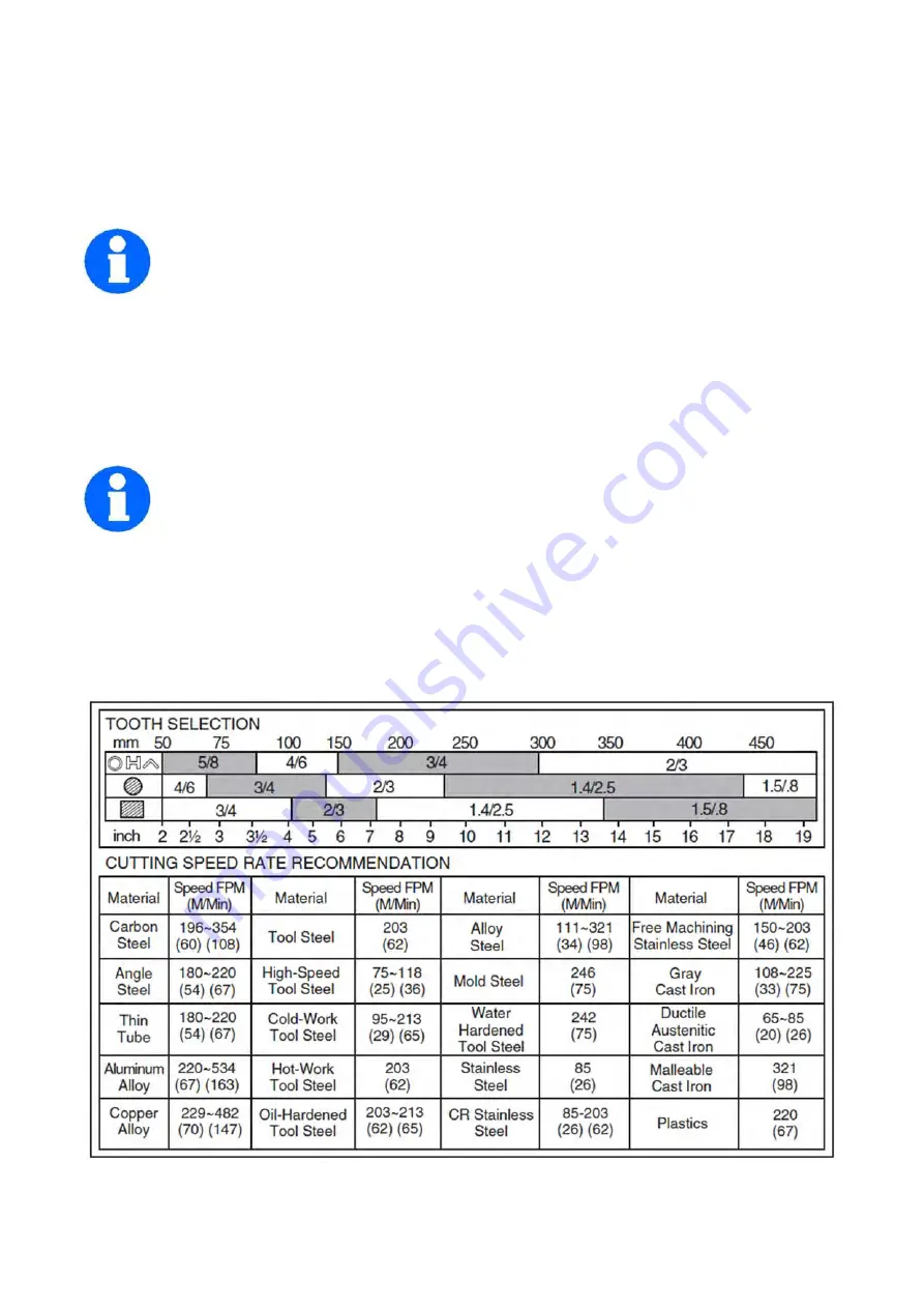
To select the correct blade TPI: 

1. Measure the material thickness. This measurement is the length of cut taken from 
where the tooth enters the workpiece, sweeps through, and exits the workpiece. 
2. Refer to the "Material Thickness" row of the blade selection chart in Figure 21, and 

read across to find the workpiece thickness you need to cut. 
3. Refer to the "Shape" of metal and "Material Type" columns, and find the shape and material to be 
cut. 
4. In the applicable row, read across to the right and find the box where the row and column 
intersect. Listed in the box is the minimum TPI recommended for the variable tooth pitch blades, 
and the TPI for bimetal raker blades in parentheses. 


Summary of Contents for 700103

Page 1: ...Code 700103 Original Instructions AT 05 11 2020 BOOK VERSION 02 MCB115SHD Swivel Head Metal Cutting Bandsaw...

Page 2: ...been issued by Laizhou Planet Machinery Co Ltd at Yutai West Street Laizhou 261400 Shandong China Mainland and complies with the relevant essential health and safety requirements 2006 42 EC EN ISO 160...

Page 3: ......

Page 4: ......

Page 5: ...ce The illustrations of the machine may be different from the illustrations in these instructions with regard to a few details However this does not have any influence on the operability of the machin...

Page 6: ...your attention to possible hazardous conditions This manual uses a series of symbols and signal words intended to convey the level of importance of the safety messages The progression of symbols is d...

Page 7: ...way from moving parts Always tie back or cover long hair Wear non slip footwear to avoid accidental slips which could cause a loss of workpiece control Personal protective equipment Dirty or contamina...

Page 8: ...he wrong cutting fluid which will lead to chip fire and possible explosion CUTTING FLUID SAFETY Always follow manufacturer s cutting fluid safety instructions Pay particular attention to contact conta...

Page 9: ...fety devices a protective cover for the V belts a saw blade casing with protective cover at the rear protective covers on the saw belt guide 1 4 1 Saw arch The saw arch of the metal cutting bandsaw is...

Page 10: ...there is a residual risk as the machine operates under electrical voltage and currents and saw blade We have used design and safety engineering to minimize the health risk to personnel resulting from...

Page 11: ...ll out the power plug before beginning any maintenance or repair All machine parts as well as all dangerous voltages must be switched off Live parts and movements of machine parts can cause severe inj...

Page 12: ......

Page 13: ...ionary measures are required or not The following factors influence the actual degree of noise to which the operator is exposed Characteristics of the working area e g size of damping behaviour other...

Page 14: ...10 2 6 Dimensions...

Page 15: ......

Page 16: ......

Page 17: ......

Page 18: ......

Page 19: ......

Page 20: ...rom the operator s position You will need to remove the rear protective cover on the saw arch to be able to carry out the checks saw blade saw blade roller shoulders Turn the front saw blade rollers s...

Page 21: ......

Page 22: ......

Page 23: ......

Page 24: ......

Page 25: ......

Page 26: ...e tensioning screw and Allen screw on the motor Place the V belt in the required position on the pulleys Tighten the V belt with the tensioning screw and Allen screw on the motor Check the V belt tens...

Page 27: ...cut use a blade with a lower TPI and a higher feed rate For a slower but smoother cut use a blade with more TPI and a lower feed rate To select the correct blade TPI 1 Measure the material thickness...

Page 28: ...place The feed rate dial controls the amount of fluid that circulates around the hydraulic cylinder which in turn controls the speed that it moves To set the feed rate 1 Raise the headstock and turn...

Page 29: ...environmental protection regulations Collecting leakages Do not re introduce liquids spilt outside the system during repair or as a result of leakage into the reserve tank collect them in a collectin...

Page 30: ......

Page 31: ...eved when you can move the saw blade with a force of about 50 N in the centre by 3mm Hand wheel Do not tension the saw blade beyond the specified limits The saw belt could be overstretched and become...

Page 32: ...whether the saw belt is parallel to the angle Loosen the screws on the saw belt guide if the angle is incorrect and adjust the saw belt guide accordingly Changing the saw blade ATTENTION The metal be...

Page 33: ......

Page 34: ...lipping on wheels 5 Low power supply voltage 6 Motor bearings are at fault 7 Plug receptacle is at fault 8 Motor connection is wired incorrectly 9 Motor has overheated 10 Motor is at fault 1 Use blade...

Page 35: ...e is too light 4 The workpiece has hard spots welds or scale is on the material 5 The blade is twisted 6 The blade is slipping on the wheels 1 Refer to Changing Blade Speed and adjust as required 2 Re...

Page 36: ...7 Diagram Part list 33 7 1 Diagram and part list for MCB128SHD Part 1...

Page 37: ...levating block 1 39 Elastic pin M3 x 20 1 40 Screw M6 x 12 6 41 Drive wheel 1 42 Drive wheel position sleeve 1 43 Drive wheel flange 2 44 Ball bearing 4 45 Retaining ring 15 1 46 Drive wheel shaft 1 4...

Page 38: ...Turning shaft 1 106 Screw M8 x 20 1 107 Sliding block 1 108 Pressing plate 2 109 Upper guard holder 1 110 Spring 1 111 Blade tebsion knob 1 112 Upper guard cover 1 113 Adjusting holder 1 114 Lock knob...

Page 39: ...Base plate 1 2 Left plate 1 3 Coach bolt 14 4 Flat wahser 18 5 Nut 14 6 Bolt 4 7 Elastic washer 4 8 Lock nut 2 9 Flat washer 2 10 Wheel 2 11 Wheel shaft 1 12 Rear plate 1 13 Right plate 1 14 Feet 2 1...

Page 40: ......

Page 41: ...e material By law they must be collected and recycled separately EU Countries Only The Axminster guarantee Buy with confidence from Axminster So sure are we of the quality we cover all parts and labou...

Reviews: