background image

Axium Music Centre Program 


AMC is an amplifier setup program, full control and tracking of the Axium amplifier zone is provided. 
The program runs on PC’s running Win XP, Win 7 or VISTA operating systems, and communicates via 

RS232, USB or Ethernet. 


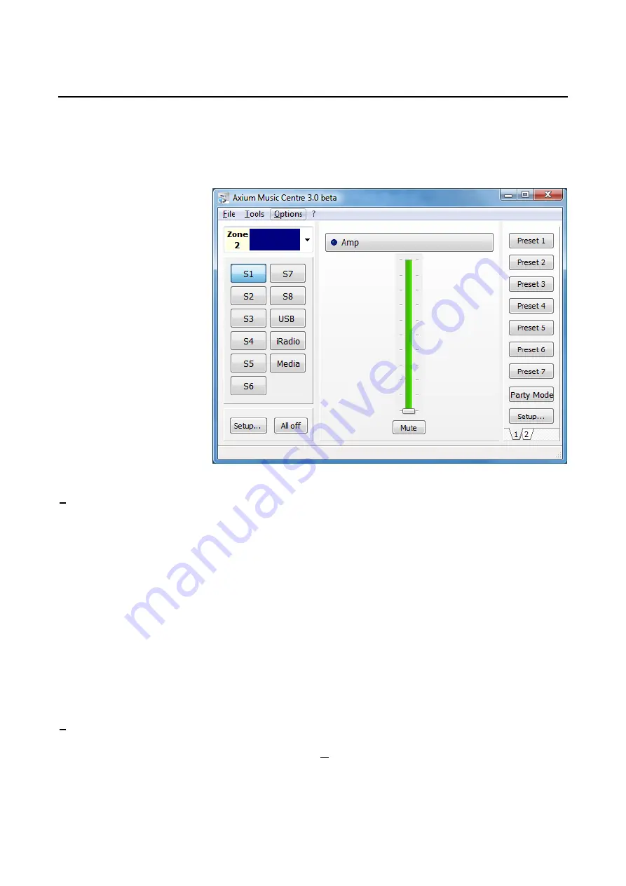
AMC’s main window provides user functionality for real-time access and control of any amplifier zone. 


When an Axium amplifier is 
first attached to a PC running 

AMC the amplifiers clock is 

automatically set to the PC’s 

current time, date and 

location. 

 
The Zone and Source buttons 

may be named by using a 

right mouse click over the 

button.  

A naming window opens 

where the name is entered. 
The name is saved in the 

connected 800DAV.  


File

 menu contains the commands:  


Network Settings:

 Opens a window where a 

Network name can edited, and the IP address 

can be set to either DHCP or static input. A 

selection is provided for synchronizing with an 

internet time server.


New window:

 Opens another AMC main 

window. This is useful for displaying and 

controlling multiple zones simultaneously  


Keypad window:


A keypad window is displayed 

where a user can cause the selected keypad on the 
network to emit its stored IR strings.


Media Servers: 

Opens a window where servers 

can be added and UNC path, Name & password 

entered. 


Download and save configuration

:  

A configuration file contains all information in an 

installation stack, i.e. Zone allocation, Zone & 

Source naming, bass, treble, loudness, max 
volume limits, preset programming etc.


Party Mode Setup: 

Opens a window where a 

Master Unit can be assigned, and source 

allocated for Party Mode application. On the 

master unit the S8 SPDIF buffered output will 

play the allocated source, and all other 

connected amplifiers in a stack will select S8. 


Upload a saved configuration:   


Upload Audio file:

 Direct AMC to the file 

location of suitable “wav” files. Click Open & 

upload the file(s) to the amplifier. 


Event Viewer: 

Open a window which displays 

a log of significant events in the amplifiers 
history. 


Exit:

 Shuts down AMC. 


Advanced: 

Provides selections for Firmware 

update and a Real time log. 

Tools

 menu contains the commands: 


Zone Assignment: 

Opens a window where 


the 800DAV Zones can assigned to between 


0 – 95. Zones on one unit must be different.


Options

 Menu contains the port assignments, 

where the program lists the detected ports. 


IR Routing Tables: 

Opens a window with a 

selection table where the IR output ports can 


be mapped to specific Controller ports. 


Select USB, Ethernet or a suitable COM port for 
RS232.  Note: Firmware update can only be 

performed using the USB connection.   


25

Summary of Contents for AX-800DAV

Page 1: ...Axium AX 800DAV Multi Zone Digital Amplifier Instruction Manual ...

Page 2: ...s been spilled or objects have fallen into the apparatus C If the apparatus has been exposed to rain or water D If the apparatus does not operate normally by following the operating instructions Adjust only those controls that are covered by the operating instructions as an improper adjustment of other controls may result in damage and will often require extensive work by a qualified technician to...

Page 3: ... earth and only use the power cord supplied Finland Laite on Liitettävä suojamaadoituskoskettimilly varustettun pistorasiaan Norway Apparatet må tilkoples jordet stikkontakt Sweden Apparaten skall anslutas till jordat uttag 5 Never Touch This Unit With Wet Hands Never handle this unit or its power cord while your hands are wet or damp If water or any other liquid gets inside this unit have it chec...

Page 4: ...mits are designed to provide reasonable protection against harmful interference in a residential installation This equipment generates uses and can radiate radio frequency energy and if not installed and used in accordance with the instructions may cause harmful interference to radio communications However there is no guarantee that interference will not occur in a particular installation If this ...

Page 5: ...Accessories 5 VDE CEE 7 7 European Plug Schuko Features 6 Front Panel Guide 8 Rear Panel Guide 9 to IEC60320 C13 socket Typical System Configuration 10 Multiple Amplifier Stacks 12 Controller Termination 13 Menu Navigation 14 WEB Application 22 Axium Music Centre Program 25 RS232 Protocol 27 Specifications 30 AS3112 Australasian Plug to IEC60320 C13 Socket Axium CD 5 ...

Page 6: ...thermal control The amplifier volume is reduced 20dB The amplifiers are shutdown until the temperature reduces below the first level Care should be taken to ensure adequate ventilation see Important safety instructions on page 1 Ethernet RS232 USB and IR control The 800DAV amplifier may be controlled and monitored via the rear Panel USB RS232 serial interface or Ethernet In multi amplifier install...

Page 7: ...c every parameter Expansion Bus Data IR Amp On are interconnected via the expansion bus One amplifier is connected to another using a standard RJ45 patch cable Connections are made between amplifiers using either of the two RJ45 expansion bus sockets Door Bell Up to 10 seconds of 44 1 KHz 16 Bit stereo sounds may be generated as part of a page preset Suitable wav files are uploaded to the unit usi...

Page 8: ...or The power indicator glows blue whenever AC power is applied 4 USB Host The port is used for Memory stick Digital music playback 5 2 4 Colour LCD Touch Panel display LCD Touch Panel display for menu guided control and programming The display is dimmed to Off after 15 minutes of inactivity 6 Chassis Feet Set high enough to provide unrestricted air flow through the chassis for convection cooling 8...

Page 9: ...g A straight through cable must be used when connecting to a PC or control system 11 Zone Preamplifier Out Analog Audio L R Zone 7 and 8 outputs 12 Analog Input Terminals Analog Audio L R inputs 13 IR Emitter Ports 3 5mm mono jacks IR1 and IR8 are used to control specific source equipment where full IR routing is assigned by the connected controller IR9 IR10 are used to control source equipment co...

Page 10: ...l System Configuration Zone 1 Gym AX KPD Zone 2 Study AX KPC Active Subwoofer Zone 3 Lounge TABLET To Ethernet router DVD PLAYER Speakers in other Zones not shown R SATELLITE RECEIVER TUNER CD PLAYER FIG 1 10 ...

Page 11: ... Axium Keypad manager program AKM Speakers Speakers in each zone are connected to the amplifier by Home Run speaker cables Video Outputs The composite video outputs are suitable for driving ONE composite video display device To avoid signal degradation home runs of appropriate 75Ω video cable should be less than 100 meters Source Equipment The 800DAV amplifier has six stereo RCA audio inputs for c...

Page 12: ...ged into the first amplifier where they are buffered and sent to the next amplifier in the stack The maximum recommended expansion is eight units Fig 2 shows inter connected amplifiers using an RJ45 expansion bus lead and RCA leads for the source Digital coax signals Amplifier Control using Ethernet RS232 or USB may be connected to any one of the 800DAV s in the stack If the media server is to be ...

Page 13: ...on and either P1 or P2 across an illuminated door bell switch The illuminated doorbell switch must have an External 12V 24V AC DC supply and current limiting resistor connected If a dry contact is to be used for PRESET Activation it must be normally closed or a FIG 3 Push to break contact The BUS RUN 0V and 12V can be connected as shown in FIG 3 EXPANSION BUS Simple Patch cable interconnection for...

Page 14: ... page provides access to the Amplifier zones Zone1 Zone 8 Selecting a Zone opens its control page Zone Control Page The eight Zones each have different background images but same function At the top of the control page the Zone and current time day are displayed The Zones button is the Home Page return The Control page provides status control for the selected Zones Standby Volume Slider Volume Up ...

Page 15: ...ick inserted in Front Panel Media Player Ethernet connection to server I Radio Accessible Internet More Functions Page When the More button is pressed and held for 1second a More functions Page opens There are four Zone specific functions that when selected navigate to setup pages EQ Levels Zones Delay There is also a System function which is not zone specific The System page is covered later Note...

Page 16: ...s status control for the selected zones Balance 20dB using slider or Left Right button Maximum Volume Limiting can be reduced over the range from 100 to the minimum of 2 using the slider or Up Down button The Back arrow button returns to the More Functions Page Delay Setup Page The Delay setup page provides a single slider and Up Down control for adjusting the Zones Audio Delay time It may be adju...

Page 17: ...text The limit is 15 regular ASCII characters Once entered select the back arrow to return to the Zones Setup Page Zone Linking Page The Zone may be linked with any other zone or zones Make the selection by scrolling through the zone list and choosing OK The Type of Zone Linking Link Volume or Link Standby may be selected When Link volume is selected the linked zone s will track the source and vol...

Page 18: ...d time zone is automatically synchronised when connected to the internet or to a PC using the USB connection However the clock settings and how the clock is displayed may be adjusted Select the Back arrow to return to the System settings Page Restore Defaults Page To restore the 800DAV to factory defaults select Yes or to return to previous menu select No Factory defaults resets the zone allocatio...

Page 19: ...ystem settings Page A Source may be named by using the phone Keypad The analog input gain can be adjusted using the Gain slider or Up Down buttons Gain is used to match the analog input levels to the Digital sources Some Analog sources have large variation in output levels The 0dB default setting is suitable for connection to high output devices like DVD players while the standard level 1Vrms is a...

Page 20: ...t up the presets using a connected PC running the Axium music centre program However Presets can be setup using the 800DAV front panel GUI The first 8 presets are accessible on the opening page To access the remaining presets select the More button Select the Back arrow to return to the System settings Page Presets 9 14 and the Page Preset may be accessed Selecting More returns to the previous pag...

Page 21: ...et Select Yes to complete and exit the Setup Preset Mode or No if you want to continue further settings changes The Set alarm button above navigates to the Alarm Preset page The Alarm time and days that it is to be activated may be selected The Alarm is set only if the Enable is set Select the Back arrow to return to the System settings Page The Zone selection button above navigates to the Zones a...

Page 22: ...ich may be used for control and monitoring of amplifier and source functions Home Page The home page provides access to the Amplifier Zones Selecting a Zone opens its control page The Zones shown above have been named If un named they are listed as Zone 1 Zone 2 etc 22 ...

Page 23: ... stick if detected Mute If the button is blue it indicates selection or ON status Because of Web browser limitations Slider setting changes are made using a positional touch on the slider The Zones button is the Home Page return Selecting the Settings button will open the Settings page Source control may be provided is setup using the Axium Keypad Manager program 23 ...

Page 24: ...Loudness Balance Slider or Left Right button Delay Slider or Up Down button Maximum Volume Limit Slider or Up Down button There is information displayed about the connected amplifiers Model and Unit ID and firmware version The amplifier heatsink temperature is also displayed The Back arrow button returns to the Zone Control Page 24 ...

Page 25: ...s Opens a window where servers can be added and UNC path Name password entered Download and save configuration A configuration file contains all information in an installation stack i e Zone allocation Zone Source naming bass treble loudness max volume limits preset programming etc Party Mode Setup Opens a window where a Master Unit can be assigned and source allocated for Party Mode application O...

Page 26: ...dB A Source will pulse red if input clipping is detected Nominally the input should be set to 6dB The Preset Setup on the AMC main page opens the Preset window Preset programming can be entered for the Presets Paging or Door Bell sound playback and triggers can be allocated Do Not Disturb DND and Alarms or timed events may be allocated Macros may be programmed where timer Source amplifier control ...

Page 27: ...election status 26 Volume BCD format 28 Video Source selection Zone Amplifiers are encoded with up to 32 zones The zone byte is used for checking if the command is applicable to the device receiving the command and if so for optionally selecting a sub device e g a bank or part of a device All Zones are addressed using FF The lower 5 bits of the zone byte represent the zone 0 31 selection i e 00000...

Page 28: ...Audio only 47 S3 Audio only Volume 04 00 A0 range Bass 05 F4 0C 12db 12db Treble 06 F4 0C 12db 12db Balance 07 EC 14 Left 20db Right 20db Send all parameters 09 XX value ignored Amplifier features 0C 00 Loudness enabled 01 Loudness disabled Maximum Volume Limit 0D 00 A0 range Link Zone 0F 00 31 zone to be linked FF for no zone linking Volume Up 11 XX value ignored Volume Down 12 XX value ignored Z...

Page 29: ... command when it is returned A Standby ON command implies that the amplifier is not muted if the amplifier was previously Off a mute command must follow the Standby command if it is muted Not all Command and Data commands are covered in this document The expected reply for the Send all Parameters command 09 is 144 bytes All command fields listed in this document are contained in the reply The repl...

Page 30: ...Vp p 75Ω Composite Buffered Video Output Level Impedance S1 S8 1 Vp p 75Ω Composite Output Level Impedance Z1 Z4 1 Vp p 75Ω Composite Interface IR Output Ten 3 5mm Jack IR1 IR10 current limited to 25mA Expansion Bus One Dual RJ45 Socket Axium Bus Summed IR Ethernet One Shielded RJ45 socket 100Base T RS232 One Isolated DB9 9600 Baud USB One USB mini B 5 pin Controller One 4 way terminal blocks 0V I...

Page 31: ......

Reviews: