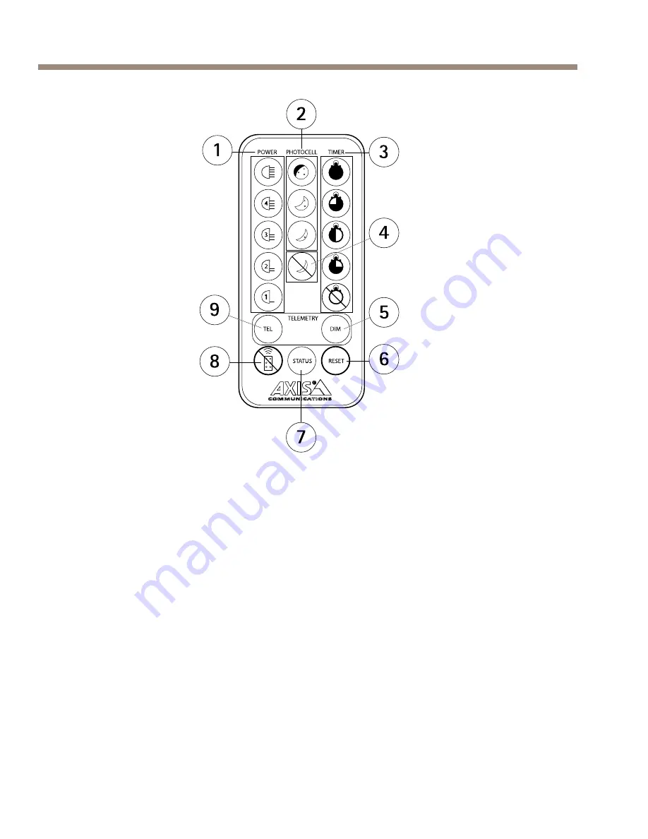
Axis T90B15 W-LED Installation Manual Download Page 12

AXIS T90B Series

1

POWiR ADJUST buttons

2

PHOTOCiLL ADJUST buttons

3

TIMiR buttons

4

Photocell disable button

5

DIM button

6

RiSiT button

7

STATUS button

8

Disable remote control setup button

9

TiLiMiTRY button

Mounting Brackets

To install the product using a compatible bracket from AXIS T90B
Mounting Accessories, see the Installation Guide delivered separately with
the mounting bracketn

12

Summary of Contents for T90B15 W-LED

Page 1: ...AXIS T90B Series AXIS T90B15 W LED AXIS T90B25 W LED AXIS T90B35 W LED AXIS T90B20 IR LED AXIS T90B30 IR LED AXIS T90B40 IR LED Installation Guide...

Page 2: ...e Disposal and Reccclins on pase 3 n A copy of the original declaration of conformity may be obtained from Axis Communications ABn See Contact Information on pase 3 n Electromagnetic Compatibility EMC...

Page 3: ...t designated collection point contact your local authority responsible for waste disposaln Businesses should contact the product supplier for information about how to dispose of this product correctly...

Page 4: ......

Page 5: ...hazardous situation which if not avoided could result in death or serious injuryn CAUTION Indicates a hazardous situation which if not avoided could result in minor or moderate injuryn NO NO NOTICi TI...

Page 6: ...ling the Axis productn Excessive force could cause damage to the productn Do not use chemicals caustic agents or aerosol cleanersn Use a clean cloth dampened with pure water for cleaningn Use only acc...

Page 7: ...ordern See pase 7 n 2n Study the hardware overviewn See pase 8 n 3n Study the specificationsn See pase 14n 4n Install the hardwaren See pase 15n Package Contents AXIS T90B Illuminator including power...

Page 8: ...AXIS T90B Series Hardware Overview Illuminator 1 Photocell 2 Cable 3 Breather sland 8...

Page 9: ...AXIS T90B Series 1 Power cable red 2 Power cable black 3 Photocell cable white 4 Photocell cable cellow 5 Telemetrc cable purple 6 Telemetrc cable oranse 9...

Page 10: ...AXIS T90B Series 1 Red LiD indicator 2 Amber LiD indicator 3 Green LiD indicator 4 Remote control receiver 5 Mountins bracket pre mounted 10...

Page 11: ...AXIS T90B Series AXIS T90B40 IR LED 1 Cables 2 Mountins bracket pre mounted 3 Bolt Optional Accessories Remote Control For information how to use the remote control see Access the Productn 11...

Page 12: ...isable button 5 DIM button 6 RiSiT button 7 STATUS button 8 Disable remote control setup button 9 TiLiMiTRY button Mounting Brackets To install the product using a compatible bracket from AXIS T90B Mo...

Page 13: ...g Mode Prosrammins Mode LED Indicator Indicated Behavior Solid Green Power on Flashing Green Remote control IR receiver error Solid Amber Illuminator receiving valid command from remote control Flashi...

Page 14: ...illuminator to turn the status LED offn Connectors and Buttons For specifications and operating conditions see pase 14n Power Connector AC DC power connector Specifications Operating Conditions Produc...

Page 15: ...AC DC max 48 W AXIS T90B40 IR LED 12 24 V AC DC max 96 W For more information about power consumption see Technical Specifications on pase 29 Install the Hardware To install the product using a compat...

Page 16: ...osure or use appropriate shielding or eye protection at distances of less than 1n5 mn Follow these installation procedures 1n If required remove the screws and move the standard bracket to the top of...

Page 17: ...n the screws and change to a diverging lens with the desired angle of illuminationn The angle of illumination should be adjusted according to the camera field of view to light the whole scene adequate...

Page 18: ...AXIS T90B Series 1 Screws 2 Diversins lens Note Adjust the vertical position of the illuminator to ensure that the field of view of the camera is illuminatedn 18...

Page 19: ...ition the illuminator adjacent to the camera and point the illuminator towards the scenen CAUTION Red cable ve Black cable ve polarity sensitive 5n Mount the power supplyn 6n Connect the illuminator t...

Page 20: ...t normally open day to normally closed night n Connect direct to camera if required to control switchover of day night camerasn Access the Product Programming Mode The illuminator has the following de...

Page 21: ...ing Mode restart the illuminatorn 1n Adjust the power see Power Adjust on pase 22n 2n Adjust the photocell sensitivity see Photocell Sensitivitc on pase 22n 3n Set the telemetry input TEL see pase 24...

Page 22: ...Select the required light intensity by using the buttons belown 1 20 of maximum 2 40 of maximum 3 60 of maximum 4 80 of maximum 5 100 of maximum Photocell Sensitivity Note When the photocell is disab...

Page 23: ...level by using the buttons belown 1 Photocell disabled 2 5 Lux On 15 Lux Off 3 10 Lux On 30 Lux Off 4 25 Lux On 50 Lux Off Telemetry Input The telemetry input wires orange and purple are designed to b...

Page 24: ...e with remote switch or inputn Under normal operating conditions a telemetry input will activate the unit only at night provided that the photocell detects low light conditionsn However if the photoce...

Page 25: ...stops the light level will stay where it was setn When the telemetry input is activated for a second time the light will start to brightenn This will continue while the telemetry input is activen This...

Page 26: ...minute 3 3 minutes 4 10 minutes 5 30 minutes 6 TiL button LED Status Indicators This status indicator function can be switched on and off by pressing the STATUS buttonn This is the only button that ha...

Page 27: ...for at least 10 secondsn When turned on the illuminator automatically re enters Programming Moden Disable remote setup once an individual illuminator has been programmed and is delivering the required...

Page 28: ...r depending on how the illuminator is being powered AC or DC n Cover the photocell fully or disable the photocell using the optional remote control and make sure the telemetry wires are shorted out or...

Page 29: ...and the illuminator may need to be reducedn Check the battery on the remote control CR2025 replace if necessaryn Make sure no other strong Infra Red source is pointing at the remote receivern Make sur...

Page 30: ...IR LED 24 W 6 W 0n15 W AXIS T90B30 IR LED 24 W 12 W 0n15 W AXIS T90B40 IR LED 96 W 24 W 0n15 W Control technology Power level Photocell sensitivity Telemetry link for remote activation if required Ti...

Page 31: ...20 x50 30 m 98 ft AXIS T90B40 IR LED 10 x10 310 m 1010 ft 35 x10 170 m 551 ft 60 x25 112 m 367 ft 80 x30 70 m 230 ft 120 x50 65 m 213 ft AXIS T90B15 W LED 10 x10 50 m 164 ft 35 x10 35 m 115 ft 60 x25...

Page 32: ...onment Outdoor Mounting Wall Ceiling Column Camera housing Approvals EN 55022 Class B EN 55024 EN 61547 EN 55015 EN 50130 4 C tick AS NZS CISPR 22 Class B FCC Part 15 Subpart B Class B ICES 003 Class...

Page 33: ...XIS T90B40 IR LED 279 x 223 x 68 mm 11 x 9 x 3 in Weight AXIS T90B15 W LED 600 g 1n3 lbs AXIS T90B25 W LED 950 g 2n1 lbs AXIS T90B35 W LED 1650 g 3n6 lbs AXIS T90B20 IR LED 950 g 2n1 lbs AXIS T90B30 I...

Page 34: ...AXIS T90B Series Warranty Information For information about Axis product warranty and thereto related information see www axis com warrantc 34...

Page 35: ...35...

Page 36: ...Installation Guide Vern M1n11 AXIS T90B Series Date May 2014 Axis Communications AB 2014 Part Non 57589...

Reviews: