


AXIS F41 Main Unit
Install the Hardware
The Axis F41 Main Unit can be placed on a table desktop or mounted on
a DIN rail. To facilitate routing the cables from the top or side remove
the 4 screws (Torx T20) and suitably realign the bottom plate under the
unit (see
Hardware Overview on page 10
). See www.axis.com for optional
accessories.
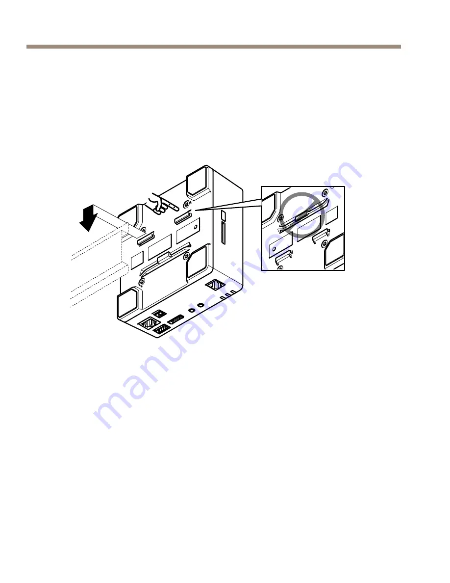
1.
If required, press to release the dummy SD card and insert an
SD memory card in the SD memory card slot.
2.
Attach the network cable to connect the unit to the network.
3.
Connect the sensor unit to the main unit with the RJ12 cable.
4.
If required, connect an AC/DC power supply to the power
connector.
5.
If required, attach the I/O cable using the 6–pin I/O connector
block to connect external input/output devices.
6.
If required, attach the audio cables to connect an active
speaker/external microphone.
20
Summary of Contents for F41
Page 8: ...8 ...
Page 17: ...AXIS F41 Main Unit 1 2 E g push button 3 4 12 V max 50 mA D S G 17 ENGLISH ...
Page 26: ...26 ...
Page 36: ...AXIS F41 Main Unit 1 2 E g push button 3 4 12 V max 50 mA D S G 36 ...
Page 42: ...42 ...
Page 46: ...46 ...
Page 56: ...AXIS F41 Main Unit 1 2 E g push button 3 4 12 V max 50 mA D S G 56 ...
Page 62: ...62 ...
Page 66: ...66 ...
Page 76: ...AXIS F41 Main Unit 1 2 E g push button 3 4 12 V max 50 mA D S G 76 ...
Page 82: ...82 ...
Page 86: ...86 ...
Page 102: ...102 ...
Page 106: ...106 ...
Page 117: ...AXIS F41 Main Unit 荷と並列に接続する必要 があります 1 2 E g push button 3 4 12 V max 50 mA D S G 117 ò ò ...
Page 123: ...123 ...