


AXIS M32 Dome Camera Series
Configure your device
•
Axis PIR detector
NO
NO
NOTICE
TICE
TICE
Disconnect the camera from power before connecting the wires. Reconnect to power after all connections are done.
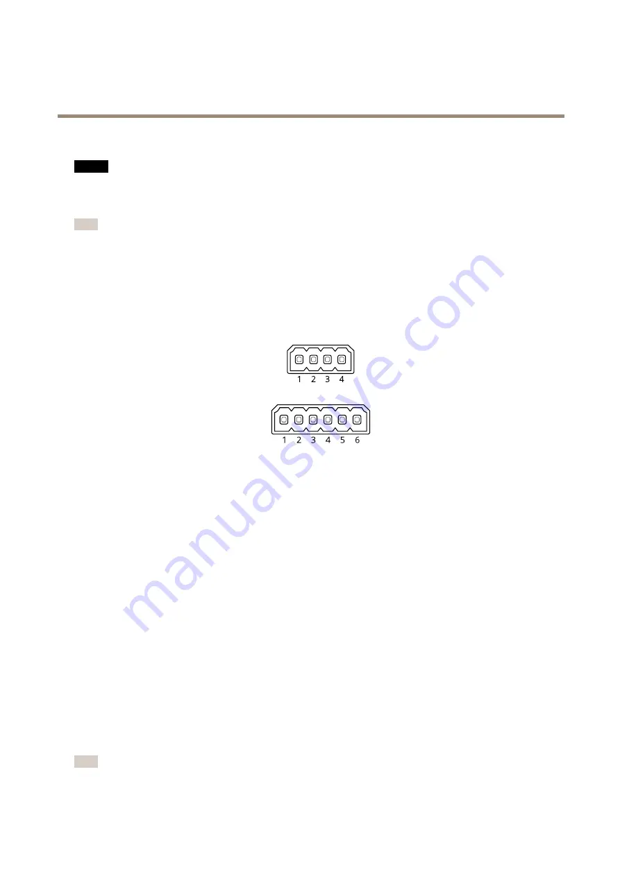
Connect the wires to the camera’s I/O connector
Note
For information on the I/O connector, see
.
1. Connect the ground wire to pin 1 (GND/-).
2. Connect the power wire to pin 2 (12V DC output).
3. Connect the I/O wire to pin 3 (I/O input).
Connect the wires to the PIR detector’s I/O connector
1. Connect the other end of the ground wire to pin 1 (GND/-).
2. Connect the other end of the power wire to pin 2 (DC input/+).
3. Connect the other end of the I/O wire to pin 3 (I/O output).
Configure the I/O port in the camera’s webpage
1. Go to
System > Accessories
.
2. Under
Direction
, select
Input
for
Port 1
.
3. Give the input module a descriptive name.
4. Under
Normal position
, select
Circuit closed
to make the PIR detector send a signal to the camera when it senses motion.
To trigger the camera to start recording when it receives a signal from the PIR detector, you need to create a rule in the camera’s
webpage.
Provide visual indication of an ongoing event
You have the option to connect the AXIS I/O Indication LED to your network camera. This LED can be configured to turn on whenever
certain events occur in the camera. For example, to let people know that video recording is in progress.
Required hardware
•
AXIS I/O Indication LED
•
An Axis network video camera
Note
AXIS I/O Indication LED should be connected to an output port.
15


