


SBC81203 LGA775 SBC User’s Manual
Jumpers and Connectors
15
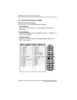
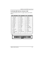
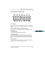
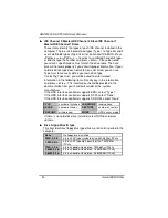
2.4.9 Front Panel Connector: CN5
Power LED
Pins 1, 3, 5 connect the system power LED indicator to its respective
switch on the case. Pin 1 is +, and pin 5 assigned to -. Pin 3 is defined
as NC.
External Speaker and Internal Buzzer Connector
Pins 2, 4, 6, 8 can be connected to the case-mounted speaker unit or
internal buzzer.
Hardware Reset
Pins 11 and 12 are designed for Hardware Rese
t
.
HDD Activity LED
This connector extends to the hard drive activity LED on the control
panel. This LED will flash when the HDD is being accessed. Pins 13
and 14 can be connected to the hard disk drive and front panel HDD
LED.
Power Button
Pins 9 and 10 connect the front panel’s ATX power button to the card,
which allows users to control ATX power on or off.
格
格
格
格式化
式化
式化
式化:::: 項目符號及編號
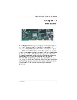
Summary of Contents for SBC81203 Series
Page 6: ...vi MEMO...
Page 10: ...SBC81203 LGA775 SBC User s Manual Introduction 4 1 3 Block Diagram 1 4 I O Bracket...
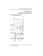
Page 12: ...SBC81203 LGA775 SBC User s Manual Jumpers and Connectors 6 2 2 Board Layout...
Page 23: ...SBC81203 LGA775 SBC User s Manual Jumpers and Connectors 17 MEMO...
Page 69: ...SBC81203 LGA775 SBC User s Manual Installation of Drivers 63 MEMO...
Page 71: ...SBC81203 LGA775 SBC User s Manual Watch Dog Timer 65 MEMO...
Page 73: ...SBC81203 LGA775 SBC User s Manual PCI IRQ Routing 67 MEMO...
Page 76: ...SBC81203 LGA775 SBC User s Manual Memory I O Address 70 A p p e n d i x D Memory I O Address...
Page 77: ...SBC81203 LGA775 SBC User s Manual Memory I O Address 71 MEMO...


