


P6157W-V2
User’s Manual
System Setup
9
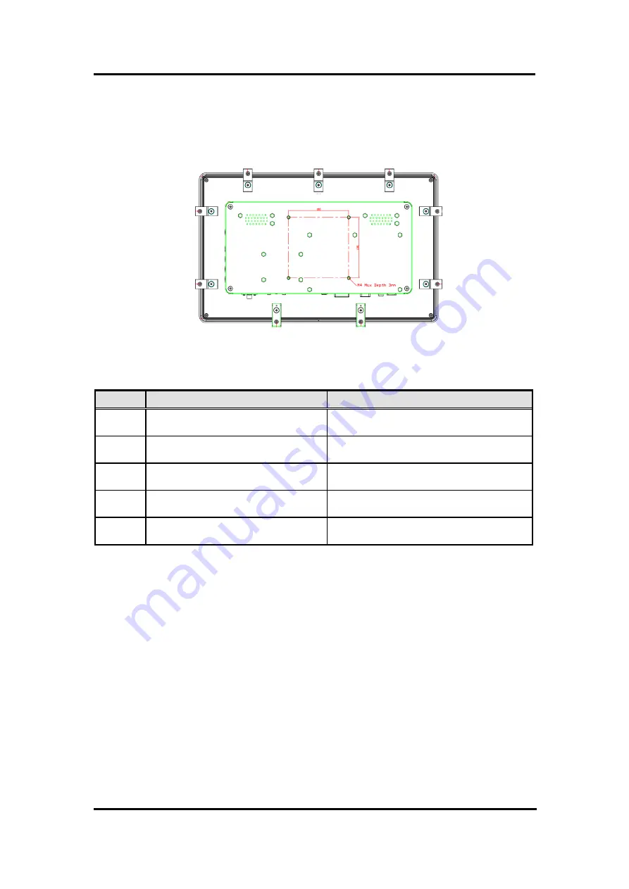
2.4
VESA Mounting
The P6171 provides VESA mount at the back of system. Screw four screws to fix the kit in the
back chassis.
2.5
System Jumper Setting
Jumper
★
Default Setting
Jumper Setting
JP1
LVDS Panel Power : 3.3V (Default)
LVDS Panel Power : 5V
Short 1-2
Short 3-4
JP3
12V DC in (VINO-12V) (Default)
24V DC in (VINO-12V)
Short 1-3, Short 2-4
Short 3-5, Short 4-6
JP4
12V DC in (Default)
24V DC to 12V DC
Short 1-3, Short 2-4
Short 3-5, Short 4-6
JP5
LCD Backlight 5V
LCD Backlight 3.3V (Default)
Short 1-2
Short 2-3
JP6
LCD Enable 5V
LCD Enable 3.3V (Default)
Short 1-2
Short 2-3
Summary of Contents for P6157W-V2
Page 1: ...P6157W V2 15 6 WXGA TFT Monitor User s Manual...
Page 10: ...P6157W V2 User s Manual 6 Introduction This page is intentionally left blank...
Page 14: ...P6157W V2 User s Manual 10 System Setup This page is intentionally left blank...
Page 16: ...P6157W V2 User s Manual 12 Supported Input Timing Modes This page is intentionally left blank...
Page 18: ...P6157W V2 User s Manual 14 OSD Operation This page is intentionally left blank...


