


MPC225-873 Series User
’s Manual
AMI BIOS Setup Utility
39
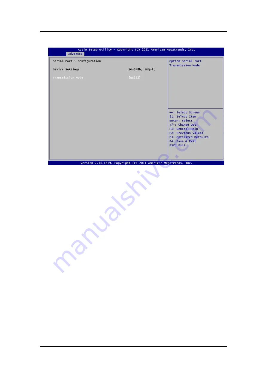
Serial Port 1 Configuration
Device Settings
The optimal setting for base I/O address is 3F8h and for interrupt request address is IRQ4.
Transmission Mode
This item allow user to set RS-232/RS-422/RS-485 transmission mode for serial port 1.
Summary of Contents for MPC225-873 Series
Page 15: ...MPC225 873 Series User s Manual Introduction 5...
Page 38: ...MPC225 873 Series User s Manual 28 Hardware Installation This page is intentionally left blank...
Page 72: ...MPC225 873 Series User s Manual 62 Watchdog Timer This page is intentionally left blank...
Page 74: ...MPC225 873 Series User s Manual 64 Digital I O This page is intentionally left blank...
Page 80: ...MPC225 873 Series User s Manual iAMT Settings 70 This page is intentionally left blank...
Page 82: ...MPC225 873 Series User s Manual Note 72 This page is intentionally left blank...


