


MANO300 Mini ITX Motherboard
16
Board and Pin Assignments
2.4.12
Power Status Header (CN15)
This is power button header (2x1-pin p=2.54mm), let customer know the power status of
this board.
2.4.13
DC12V/5V Power Output Connector (CN16)
This is a 4x1-pin p=2.54mm connector for DC +12V and +5V power output.
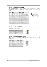
2.4.14
PS/2 Keyboard and Mouse Connector (CN17)
The motherboard has two 6-pin mini-DIN PS/2 connectors; green for mouse and purple
for keyboard.
Pin
Signal
1
PWR+
2
PWR-
Pin
Signal
1
+12V
2
GND
3
GND
4
+5V
Pin Signal
Pin
Signal
1
K/B Data
7
M/S Data
2
NC
8
NC
3
GND
9
GND
4
+5V
10
+5V
5
K/B CLK
11
M/S CLK
6
NC
12
NC
1
Summary of Contents for MANO300 Series
Page 1: ...MANO300 Series Intel Braswell SoC CPU Mini ITX Motherboard User s Manual ...
Page 6: ...vi This page is intentionally left blank ...
Page 10: ...MANO300 Mini ITX Motherboard 4 Introduction 1 4 Block Diagram ...
Page 32: ...MANO300 Mini ITX Motherboard 26 Hardware Description This page is intentionally left blank ...


