background image

IPC970 Series U

ser’s Manual 


Hardware Installation 

41


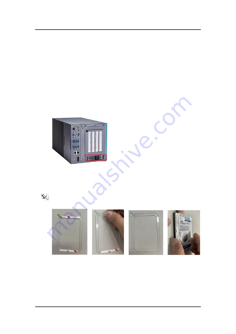
2.5  Installing the Hard Disk Drive and NVMe SSD


The IPC970 offers two convenient external 

2.5” SSD/HDD drive bays, one NVMe SSD socket 

and  a  optional    internal  SSD/HDD  bracket  kit  for  installation.  Please  refer  to  the  following 

instructions and illustrations for then installation of storage drives. 

Step 1

   Turn off the system. 

Step 2

   Disconnect the power connector. 


2.5.1  Installing external SSD/HDD 

Step 1     

Open the SSD/HDD tray 


Step 2

      Align  the connector of the  SSD/HDD with the  SATA slot  on the  main  board. Then 

insert the SSD/HDD into the SSD/HDD bay. 

Step 3     

The external SSD/HDD installation complete. 

 Note: When using 7mm height HDD/SDD, please take the HDD spacer out of the 

accessory box and  follow the steps below to stick it on HDD/SSD. 

Summary of Contents for IPC970

Page 1: ...IPC970 Industrial and Fanless Computer User s Manual...

Page 2: ...sefulness of any information in this document Axiomtek does not make any commitment to update the information in this manual Axiomtek reserves the right to change or revise this document and or produc...

Page 3: ...voltage of the power source is correct before connecting the equipment to the power outlet 5 Turn OFF the system power before cleaning Clean the system using a cloth only Do not spray any liquid clea...

Page 4: ...lean any single part or component for the computer please read and understand the details below fully When you need to clean the device please rub it with a piece of dry cloth 1 Be cautious of the tin...

Page 5: ...ing alcohol You may moisten a piece of cloth a bit with some water or rubbing alcohol and rub it on the computer Unknown solvents may be harmful to the plastics parts Vacuum cleaner Vacuuming dust dir...

Page 6: ...n case computers are out of order or are no longer in use Trademark Acknowledgments Axiomtek is a trademark of Axiomtek Co Ltd Intel and Pentium are registered trademarks of Intel Corporation Windows...

Page 7: ...i Fi Bluetooth CN12 22 1 7 10 LAN Connector CN13 23 1 7 11 DC in Phoenix Power Connector CN14 24 1 7 12 SATA Power Connector SCN2 SCN3 SCN4 24 1 7 13 SATA Connector SATA1 SATA2 24 1 7 14 AT ATX Power...

Page 8: ...viii SECTION 3 AMI BIOS UTILITY 55 3 1 Starting 55 3 2 Navigation Keys 56 3 3 Main Menu 57 3 4 Advanced Menu 58 3 5 Chipset Menu 71 3 6 Security Menu 80 3 7 Boot Menu 81 3 8 Save Exit Menu 82...

Page 9: ...nectors Package List 1 1 General Description The IPC970 is an embedded system that supports the LGA1200 socket for Intel Xeon and 10th generation CoreTM i7 i5 i3 processors The IPC970 supports Windows...

Page 10: ...metlake XeonW 1250TE 35W 6 12 2 4 GHz 3 8 GHz Cometlake XeonW 1270E 80W 6 16 3 4 GHz 4 7 GHz Cometlake i7 10700E 65W 8 16 2 9 GHz 4 8 GHz Cometlake i7 10700TE 35W 8 16 2 0 GHz 4 4 GHz Cometlake i5 105...

Page 11: ...ports 10G two USB3 2 Gen 1 ports 5G HDD access LED and three user s LEDs Two G E LAN ports i225 LM and i211 AT One Ground Terminal Flexible IO AX93511 4 x RS 232 422 485 module default RS 232 AX93512...

Page 12: ...ed to use Gen 3 SSD on IPC970 Expansion Slot One on board full size PCI Express Mini Card slot USB PCIe interface w one SIM slot One M 2 Key E 2230 socket w two antenna openings One M 2 Key B 3042 305...

Page 13: ...100E 65W 4 8 3 2 GHz 10 50 i3 10100TE 35W 4 8 2 3 GHz 10 60 G6400TE 35W 2 4 3 2 GHz 10 60 Note The IPC system may cause CPU frequency hopping when operating in an extremely high temperature environmen...

Page 14: ...troduction Humidity 10 90 Non condensing Dimensions 190 mm W x 192 mm H x 360 mm D w internal fan module 190 mm W x 192 mm H x 372 6 mm D w external fan module Note All specifications and images are s...

Page 15: ...IPC970 Series User s Manual Introduction 7 1 3 Block Diagrams and Dimensions The following figures show you the motherboard and system block diagrams of the IPC970...

Page 16: ...IPC970 Series User s Manual 8 Introduction The following diagrams show you the system dimensions IPC970 system...

Page 17: ...IPC970 Series User s Manual Introduction 9 IPC970 system w optional 5G antenna bracket...

Page 18: ...Series User s Manual 10 Introduction 1 4 Outlets The following figures show you the outlets of the IPC970 No Description 1 1 x SSD HDD access LED 3 x user s LED 2 1 x Power on off button w LED 3 1 x L...

Page 19: ...m I O module 1 AX93511 4 x RS 232 422 485 module default RS 232 optional 2 AX93512 2 x RS 232 422 485 with isolated 1 5kVDC 8 in 8 out with isolated 1 5kVDC DIO module optional 3 AX93516 4 x RS 232 42...

Page 20: ...reset switch cable x 1 Extension holder bracket kit x 1 HDD spacer x 1 Graphics card power cable x 2 M 2 NVMe SSD bracket kit x1 Item Description Outlook Usage Qty 1 M2X3L screw 5G card Key B M 2 2280...

Page 21: ...6 32 6L screw Holder bracket for add in card 5 5 Expansion holder bracket Add in card 1 6 Expansion holder bracket Add in card 1 7 Expansion holder bracket Add in card 1 8 Holder bracket Add in card...

Page 22: ...witch cable 1 13 Add on card power cable L 400mm Add on card 2 14 Terminal block Power switch 1 15 NVMe SSD thermal pad NVMe SSD 2 16 NVMe SSD bracket NVMe SSD 1 16 M3x6L screw NVMe SSD 2 If you canno...

Page 23: ...per Open Closed Pin1 2 Closed Jumper Descriptions Setting JP2 Clear RTC Normal 1 2 close JP5 J61 DELAY Function SW 1 2 close 1 6 1 Restore BIOS Optimal Defaults JP3 Put jumper clip to pin 2 3 for a fe...

Page 24: ...Audio connector CN4 VGA connector CN5 HDMI connector CN6 M 2 KeyB 3042 3050 CN7 USB3 0 connector CN8 CN10 Full size PCI Express Mini Card slot CN11 M 2 KeyE 2230 CN12 LAN connector CN13 DC in Phoenix...

Page 25: ...IN 4 GND Pins Signals Color 1 GND Black 2 GND Black 3 FP_PSIN Red 4 HW_RST Blue 1 7 2 SIM Card Slots CN3 CN9 The IPC970 includes one SIM slot CN3 on the top side of the system for inserting the SIM ca...

Page 26: ...g high definition video and high resolution audio over a single cable Pins Signals Pins Signals 1 HDMI OUT_DATA2 11 GND 2 GND 12 HDMI OUT Clock 3 HDMI OUT_DATA2 13 N C 4 HDMI OUT_DATA1 14 N C 5 GND 15...

Page 27: ...GPIO_11 24 GPIO_7 25 DPR 26 GPIO_10 27 GND 28 GPIO_8 29 USB3 1 Tx 30 UIM RESET 31 USB3 1 Tx 32 UIM CLK O 33 GND 34 UIM DATA I O 35 USB3 1 Rx 36 UIM PWR O 37 USB3 1 Rx 38 NC 39 GND 40 GPIO_0 41 PERn0...

Page 28: ...compliant with USB 3 2 10Gb s ideal for installing USB peripherals such as scanners cameras USB devices etc Pins Signal USB Port 0 A1 B1 C1 D1 USB_VCC 5V level standby power A2 B2 C2 D2 USB_Data A3 B...

Page 29: ...No use 4 GND 5 No use 6 1 5V 7 CLKREQ 8 No use 9 GND 10 No use 11 REFCLK 12 No use 13 REFCLK 14 No use 15 GND 16 No use 17 No use 18 GND 19 No use 20 W_DISABLE 21 GND 22 PERST 23 PE_RXN3 SATA_RXP 24...

Page 30: ...GND 19 NC 20 NC 21 NC 22 NC 23 NC 24 CONNECTOR KEY E 25 CONNECTOR KEY E 26 CONNECTOR KEY E 27 CONNECTOR KEY E 28 CONNECTOR KEY E 29 CONNECTOR KEY E 30 CONNECTOR KEY E 31 CONNECTOR KEY E 32 NC 33 GND 3...

Page 31: ...I_DA TX Bidirectional or transmit Data L3 BI_DB RX Bidirectional or receive Data L4 BI_DC N C Bidirectional or not connected L5 BI_DC N C Bidirectional or not connected L6 BI_DB RX Bidirectional or re...

Page 32: ...CN1 SCN2 for interfacing to SATA 2 5 HDD power supply Pins Signals 1 12V level 2 GND 3 GND 4 5V level 1 7 13 SATA Connector SATA1 SATA2 These Serial Advanced Technology Attachment Serial ATA or SATA c...

Page 33: ...llows users to control SBC87519 power on off Function Description On Turn on off system Off Keep system status 1 7 15 AT ATX Switch SSW1 If you set AT ATX switch to AT mode the system will be automati...

Page 34: ...can be configured via BIOS settings COM1 COM2 COM3 COM4 Pins RS 232 RS 422 RS 485 1 DCD Data Carrier Detect TX Data 2 RXD Receive Data TX Data 3 TXD Transmit Data RX No use 4 DTR Data Terminal Ready...

Page 35: ...rts RS 232 422 485 can be configured via BIOS settings COM1 COM2 DIO1 DIO2 CN1 COM1 CN2 COM2 Pins RS 232 RS 422 RS 485 1 DCD Data Carrier Detect TX Data 2 RXD Receive Data TX Data 3 TXD Transmit Data...

Page 36: ...ction Pin Function 1 Common1 PWR 1 Common2 PWR 2 DO10 2 DO20 3 DO11 3 DO21 4 DO12 4 DO22 5 DO13 5 DO23 6 Common 1 PWR 6 Common 2 PWR 7 External 1 Power 7 External 2 Power 8 DI10 8 DI20 9 DI11 9 DI21 1...

Page 37: ...lated digital input channels accepts 0 30 VDC with sink type and source type Isolated Digital Output The figure shows how to connect between an output channel and the system If an external 5 30 VDC vo...

Page 38: ...e configured via BIOS settings COM1 COM2 COM3 COM4 Pins RS 232 RS 422 RS 485 1 DCD Data Carrier Detect TX Data 2 RXD Receive Data TX Data 3 TXD Transmit Data RX No use 4 DTR Data Terminal Ready RX No...

Page 39: ...B 3 0 5Gb s providing ideal interfaces for installing USB peripherals such as scanners cameras and other USB devices Pins Signal USB Port 0 Pins Signal USB Port 1 1 USB_VCC 5V level standby power 1 US...

Page 40: ...ia BIOS settings COM1 COM2 Pins RS 232 RS 422 RS 485 1 DCD Data Carrier Detect TX Data 2 RXD Receive Data TX Data 3 TXD Transmit Data RX No use 4 DTR Data Terminal Ready RX No use 5 GND Ground No use...

Page 41: ...ase T 100 10 Base T Descriptions L1 BI_DA TX Bidirectional or Transmit Data L2 BI_DA TX Bidirectional or Transmit Data L3 BI_DB RX Bidirectional or Receive Data L4 BI_DC N C Bidirectional or Not Conne...

Page 42: ...IPC970 Series User s Manual 34 Introduction This page is intentionally left blank...

Page 43: ...ding your warranty by opening the computer or replacing your processor Instructions 1 Make sure that your system can accommodate the Intel Coree i7 i5 i3 Celeron Processors that you want to install Ch...

Page 44: ...he heatsink cover you can locate the CPU socket as marked Align pins of the CPU with the pin holes of the socket Beware of the CPU s orientation by aligning the arrow mark on the CPU with the arrow ke...

Page 45: ...h a Mini card slot and a M 2 Key E 2230 socket for users to install a wireless LAN card Please refer to the following instructions and illustrations for the installation of the wireless LAN Step 1 Tur...

Page 46: ...ied extended bracket when using a half size Mini card 2 3 Installing the 5G Module The IPC970 comes with a M 2 Key B 3040 3050 socket for users to install a 5G wireless module Please refer to the foll...

Page 47: ...key B socket and push it down firmly and screw the card tightly to the mainboard Then insert the SIM module into the SIM slot Step 5 Remove the antenna plugs from the 5G bracket install the antennas...

Page 48: ...odule Step 1 Turn off the system Step 2 Disconnect the power connector Step 3 Loosen 7 screws to remove the side cover from the chassis Step 4 Install the U DIMM into the socket and push it firmly dow...

Page 49: ...illustrations for then installation of storage drives Step 1 Turn off the system Step 2 Disconnect the power connector 2 5 1 Installing external SSD HDD Step 1 Open the SSD HDD tray Step 2 Align the...

Page 50: ...scription of the 2 5 HDD Tray is as shown below 2 5 2 Installing SSD HDD and NVMe SSD Step 1 Open the SSD HDD NVMe SSD cover on the bottom side of the IPC970 Step 2 Take the SSD HDD bracket and its sc...

Page 51: ...the SSD HDD into the bay and screw the bracket Installation is complete Step 4 Take the NVMe bracket thermal pads and its screws from the accessory box and stick a thermal pad on socket then insert t...

Page 52: ...PCIe expansion card into the system is described below Step 1 Turn off the system Step 2 Disconnect the power connector Step 3 Loosen 7 screws to remove the side cover from the chassis 2 6 1 Installi...

Page 53: ...t to the chassis to secure the add on card in place Step 4 Close the side cover back to the chassis and fasten all screws The installation is complete Note When installing an add on card with height l...

Page 54: ...illustrated below Or Step 6 Fasten the holder bracket in the chassis adjust the screw position of the extension bracket to fix the add on card and then screw it Note Please plug two graphics card pow...

Page 55: ...rnal fan module or an optional external fan module The procedure of installing the fan module into system is illustrated below Step 1 Turn off the system Step 2 Disconnect the power connector Step 3 L...

Page 56: ...he fan on the fan bracket and screw the fan to the bracket Step 6 Screw the fan module to the system chassis and plug the fan cable to the fan connector on the riser Step 7 Close the side cover back t...

Page 57: ...ng heat dissipation potential a space of 20mm must be left between the add on card and the system Slot Slot 1 PCIe x8 Slot 2 PCIe x8 Slot 3 PCIe x16 Height 52 6 123 4 mm 52 6 123 4 mm 52 6 123 4 mm Wi...

Page 58: ...n the riser card is in use When the internal fan is installed and the add on card s power connector on the riser card is not in use 336 472mm 336 472mm 336 472mm When the external fan is installed and...

Page 59: ...add on card s power connector on the riser card is not in use 362 472mm 362 472mm 362 472mm 2 7 Installing the foot pads Step 1 Turn off the system Step 2 Disconnect the power connector Step 3 Take th...

Page 60: ...es User s Manual 52 Hardware Installation 2 8 Wall mounting The IPC970 provides a wall mount kit for optional mounting Step 1 Turn off the system Step 2 Disconnect the power connector Step3 Remove fou...

Page 61: ...IPC970 Series User s Manual Hardware Installation 53 Step4 Assemble the wall mount bracket to the chassis and tighten six M4x6L screws Wall mounting installation is complete...

Page 62: ...IPC970 Series User s Manual 54 Hardware Installation This page is intentionally left blank...

Page 63: ...ng To enter the setup screens follow the steps below 1 Turn on the computer and press the Del key immediately 2 After you press the Del key the main BIOS setup menu displays You can access the other s...

Page 64: ...en Plus Minus The Plus and Minus Arrow keys allow you to change the field value of a particular setup item Tab The Tab key allows you to select setup fields F1 The F1 key allows you to display the Gen...

Page 65: ...Main tab System Time Date can be set up as described below The Main BIOS setup screen is shown below System Date Time Use this option to change the system time and date Highlight System Time or System...

Page 66: ...o allows users to set configuration of the CPU and other system devices You can select any of the items in the left frame of the screen to go to the sub menus ACPI Settings CPU Configuration CSM Confi...

Page 67: ...ation can be set in ACPI Settings A description of the selected item appears on the right side of the screen ACPI Sleep State Select the highest ACPI sleep state the system will enter when the suspend...

Page 68: ...IPC970 Series User s Manual 60 AMI BIOS Utility...

Page 69: ...Virtualization Technology This item allows a hardware platform to run multiple operating systems separately and simultaneously enabling one system to virtually function as several systems Note Select...

Page 70: ...IPC970 Series User s Manual 62 AMI BIOS Utility CSM Configuration...

Page 71: ...IPC970 Series User s Manual AMI BIOS Uitlity 63 Hardware Monitor This screen monitors hardware health...

Page 72: ...IPC970 Series User s Manual 64 AMI BIOS Utility PCH FW Configuration Display ME firmware information...

Page 73: ...S Uitlity 65 PCI Subsystem Settings This screen allows you to set PCI Subsystem mode PCI Latency Timer Set the value to be programmed into PCI Latency Timer Register VGA Palette Snoop Enables or Disab...

Page 74: ...Configuration Native PCIE Enable Bit PCIe Native control n 0 Hot Plug n 1 SHPC Native Hot Plug control n 2 Power Management Events n 3 PCIe Advanced Error Reporting control n 4 PCIe Capability Structu...

Page 75: ...r feature The default is Enabled SATA Mode Selection Determine how SATA controller s operate Operation mode options are RAID and AHCI Advanced Host Controller Interface The default is the AHCI mode SA...

Page 76: ...Manual 68 AMI BIOS Utility SATA Device Type Identify the SATA port is connected to a solid state drive SSD or hard disk drive HDD Trusted Computing Select the Security Device Support to enable or disa...

Page 77: ...ys all detected USB devices Legacy USB Support Enables Legacy USB support AUTO option disables legacy support if no USB devices are connected XHCI Hand off This is a workaround for OSes without XHCI h...

Page 78: ...SB mass storage device Start Unit command time out Device power up delay Maximum time the device will take before it properly reports itself to the Host Controller Auto uses default value for a Root p...

Page 79: ...tion This screen shows System Agent information and provides functions for specifying related parameters For items marked with please press Enter for more options You can select any of the items in th...

Page 80: ...IPC970 Series User s Manual 72 AMI BIOS Utility...

Page 81: ...IPC970 Series User s Manual AMI BIOS Uitlity 73 Graphics Configuration Open the sub menu for parameters related to graphics configuration...

Page 82: ...IPC970 Series User s Manual 74 AMI BIOS Utility Memory Configuration Open the sub menu for information related to system memory...

Page 83: ...IPC970 Series User s Manual AMI BIOS Uitlity 75 PEG Port Configuration Open the sub menu for parameters related to PEG port configuration...

Page 84: ...IPC970 Series User s Manual 76 AMI BIOS Utility PCH IO Configuration For items marked with please press Enter for more options...

Page 85: ...IPC970 Series User s Manual AMI BIOS Uitlity 77 HD Audio Configuration...

Page 86: ...IPC970 Series User s Manual 78 AMI BIOS Utility PCI Express Configuration...

Page 87: ...IPC970 Series User s Manual AMI BIOS Uitlity 79 USB Configuration...

Page 88: ...menu allows users to change the security settings for the system Administrator Password This item indicates whether an administrator password has been set installed or uninstalled User Password This...

Page 89: ...ng Bootup NumLock State Use this item to select the power on state for the keyboard NumLock Quiet Boot Select to display either POST output messages or a splash screen during boot up Launch PXE OpROM...

Page 90: ...s to save changes and exit Discard Changes and Exit Select this option to quit Setup without making any permanent changes to the system configuration and return to Main Menu Select Discard Changes and...

Page 91: ...manent changes to the system configuration Select Discard Changes from the Save Exit menu and press Enter Select Yes to discard changes Restore Defaults After selecting this option all the settings wi...

Reviews: