AXIOMTEK GOT321W-502-PCT/FR User Manual Download Page 25

GOT321W-502-PCT/FR


User’s  Manual 

Hardware  and  Installation


19


Step 3 

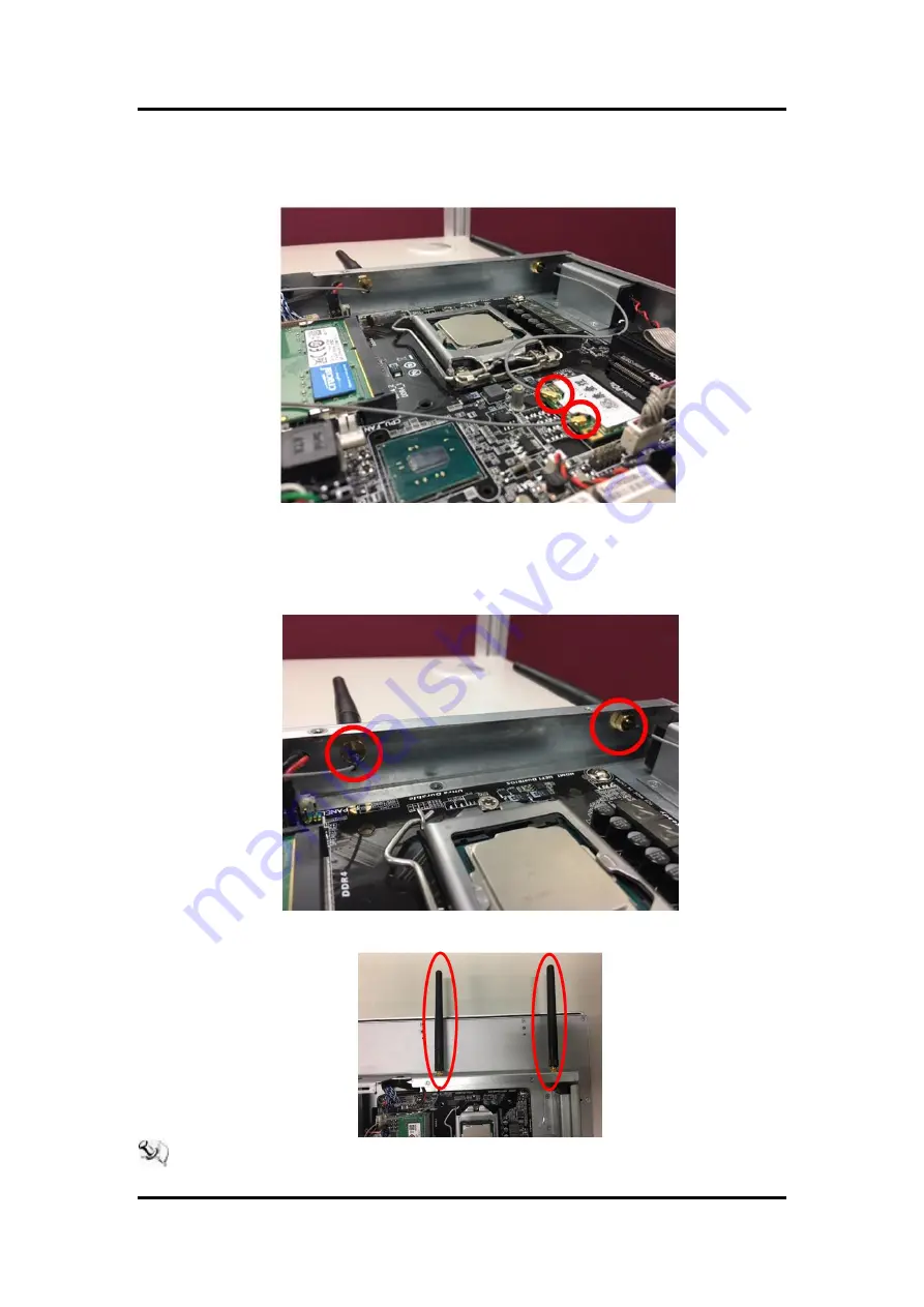
Locate the antenna cable and connect it to the wireless LAN card (see Figure 
2-12). 


Figure 2-12 Connecting the antenna to the wireless LAN card 


Step 4 

Remove  the  antenna  plug  from  the  top  of  back  cover

and  then  install  the 

antenna on the antenna connector (see Figures 2-13 and 2-14). 


Figure 2-13 The Antenna outlet (internal view) 


Figure 2-14 The Antenna outlet (external view) 


NOTE:  Please use an extended bracket when using a half-size Mini card. 


Summary of Contents for GOT321W-502-PCT/FR

Page 1: ...GOT321W 502 PCT FR All in One 21 5 FHD Fanless 10 Point P CAP Resistive Touch PANEL PC User s Manual...

Page 2: ...tion in this manual Axiomtek reserves the right to change or revise this document and or product at any time without notice No part of this document may be reproduced stored in a retrieval system or t...

Page 3: ...cover for maintenance is a must only a trained technician is allowed to do so Integrated circuits on computer boards are sensitive to static electricity To avoid damaging chips from electrostatic disc...

Page 4: ...per 11 2 2 2 COM Port Connector 11 2 2 3 Ethernet Connector 12 2 3 Mounting Methods 13 2 4 Hardware Installation 15 2 4 1 Installing a HDD 15 2 4 2 Installing a DRAM 16 2 4 3 Installing a CPU 17 2 4 4...

Page 5: ...ers 31 4 2 Touch Screen 32 Appendix A Watchdog Timer 33 About Watchdog Timer 33 How to Use Watchdog Timer 33 WDT Sample Program 34 ITE 8620 Datasheet about Watch Dog register description 35 Appendix B...

Page 6: ...vi This page is intentionally left blank...

Page 7: ...7 Embedded Windows 8 Windows 8 Embedded Windows 10 Windows 10 IoT and variety applications This fanless platform was especially designed for operation in a harsh environment including steel refinery...

Page 8: ...GOT321W 502 PCT is design with a user friendly multi PCAP touch Users can operation it with direct touch The surface hardness is up to 7H good for applications of anti scratch purpose 21 5 Resistive...

Page 9: ...32GB BIOS AMI UEFI BIOS I O System Standard I O 2 x RS 232 422 485 4 x USB 3 0 2 x RJ 45 1 x HDMI 1 4b 1 x VGA 1 x Display Port 1 2 2 x Power input 1 x AT ATX switch 1 x Remote power switch 1 x Line O...

Page 10: ...nsions of the main body 547 59 x 339 05 x 75 6 mm Operating temperatures 0 C to 40 C Relative humidity 20 to 90 40 C Non condensing System power input DC power input 12V 19V 24V DC in with Phoenix pow...

Page 11: ...duction 5 1 3 Dimensions and Outlines Diagram 1 1 shows the dimensions and outlines of the front panel of the GOT321W 502 PCT FR Diagram 1 1 Front dimensions and outline of the GOT321W 502 PCT FR Fron...

Page 12: ...T321W 502 PCT FR FR FR User s Manual 6 Introduction Diagram 1 2 Back outline of the GOT321W 502 PCT FR Diagram 1 3 Cutting out dimensions of the GOT321W 502 PCT FR Cut out dimensions 534 69 x 326 15 m...

Page 13: ...on 7 1 4 I O Outlets Please refer to Figures 1 2 and 1 3 for I O locations of the GOT321W 502 PCT FR Figure 1 2 Bottom view of the GOT321W 502 PCT FR Figure 1 3 Side view of the GOT321W 502 PCT FR Fig...

Page 14: ...T321W 502 PCT FR unit x 1 Driver disc x1 various OS versions and bundles available Phoenix connector x 1 DC power version only Panel mount kit x 16 Screws x 4 fix HDD under the HDD bracket NOTE Barebo...

Page 15: ...e I O This Section is describing hardware installation including the following subsections Board Layout Jumper and Connector Setting Mounting Methods Hardware Installation Connecting the Power Input 2...

Page 16: ...pins to close the pins And remove jumper clip from 2 jumper pins to open the pins Diagram 2 1 illustrates how to set up a jumper Diagram 2 1 Definitions of pin settings Pins 1 2 open Pins 1 2 close Pi...

Page 17: ...turn off your computer and unplug the power cord from the power outlet before clearing the CMOS values After system restart go to BIOS Setup to load factory defaults select Load Optimized Defaults or...

Page 18: ...established by plugging one end of the Ethernet cable into this RJ 45 connector and the other end phone jack to a 1000 100 10 Base T hub Please refer to Table 2 2 for detailed pin assignment for LAN1...

Page 19: ...321W 502 PCT FR namely panel VESA wall desktop mount The GOT321W 502 PCT FR is designed for panel mount application To mount the GOT321W 502 PCT FR the standard set of mounting kit 16 pcs included in...

Page 20: ...ed by way of VESA mount which is in the dimensions of 100x100 mm Simply fix four screws to fasten the kit from the back chassis as shown in Diagram 2 5 Additionally users can otherwise go for wall mou...

Page 21: ...rive HDD bracket for users to install a 2 5 support 7mm 9 5mm SATA HDD Please follow the steps Step 1 Refer to Section 2 1 to open the back cover Step 2 Unfastening the screw to slide open as shown in...

Page 22: ...the screw see Figure 2 6 Figure 2 6 Connecting cables to connectors 2 4 2 Installing a DRAM The GOT321W 502 PCT FR provides two DDR4 SO DIMM socket that supports system memory up to 32GB Please follow...

Page 23: ...4 3 Installing a CPU The CPU is socket type on main board that supports Intel 6 7 th core i processor Please follow four steps below to install a CPU Step 1 move the iron bar Step 2 open the cover Ste...

Page 24: ...fer to the following instructions and illustration for the installation of the wireless LAN card Step 1 Refer to Section 2 1 to open the back cover then locate the Mini card slot on the mainboard Figu...

Page 25: ...ure 2 12 Connecting the antenna to the wireless LAN card Step 4 Remove the antenna plug from the top of back cover and then install the antenna on the antenna connector see Figures 2 13 and 2 14 Figur...

Page 26: ...R is equipped with a Phoenix type of power connector which adopts 12V 19 24V DC in Please follow the signs on the power connector to connect DC power source see Figure 2 15 Figure 2 15 The power conne...

Page 27: ...s are used to select a setup screen and Up Down The and keys are used to select a setup screen or sub screen and Plus Minus The and keys you are used to change the field value of a particular setup it...

Page 28: ...GOT321W 502 PCT FR FR FR User s Manual 22 AMI BIOS Setup Utility 3 2 M I T Figure 3 1 M I T M I T Current Status This screen provides information on CPU memory frequencies parameters...

Page 29: ...nguage Selects the default language used by the BIOS System Date Sets the system date The date format is week read only month date and year Use Enter to switch between the Month Date and Year fields a...

Page 30: ...assword is required every time the system boots or only when you enter BIOS Setup After configuring this item set the password s under the Administrator Password User Password item Setup A password is...

Page 31: ...ou to choose whether to enable Intel PTT technology NOTE PPT only support OS WIN10 if OS is WIN7 please set to Disabled SW Guard Extensions SGX This option allows you to choose whether to enable the I...

Page 32: ...ics memory size Options are 32M 512M Default 64M DVMT Total Gfx Mem It allows user to allocate the DVMT memory size of the onboard graphics Options are 128M 256M MAX Default 256M PCH LAN Controller LA...

Page 33: ...Mode AT ATX power modes can both be used on the GOT321W 502 Panel PC The selection is made through an AT ATX switch on the I O interface panel AT The system will automatically start when plug in powe...

Page 34: ...stant Off Press the power button and then the system will be turned off instantly Default Delay 4 Sec Press and hold the power button for 4 seconds to turn off the system If the power button is presse...

Page 35: ...vice to boot immediately Press Enter on the device you select and select Yes to confirm Your system will restart automatically and boot from that device Save Profiles This function allows you to save...

Page 36: ...GOT321W 502 PCT FR FR FR User s Manual 30 AMI BIOS Setup Utility This page is intentionally left blank...

Page 37: ...nstalling 4 1 1 Installing System Drivers Win 7 Insert Driver CD and select the Drivers Step 1 Under directory there are more file folders as shown below Figure 4 1 Different folders of Win7 and Win10...

Page 38: ...Screen 10 points Projected Capacitive type Touch Screen Controller eGalax EXC3188 Touch Screen Controller IC Communications USB interface Resolution Depends on screen resolution Sensor 25 PPI Power I...

Page 39: ...alue and must reset it periodically If the counter ever reaches zero which means the software has crashed the system will reboot How to Use Watchdog Timer The I O port base addresses of watchdog timer...

Page 40: ...1 Enable 0 Disable Bit 5 WDT Time out Extra Select 1 64ms x WDT Timer out value default 3 5s 0 Determined by WDT time out value select 1 bit 7 Bit 4 WDT Output through PWRGD Enable 1 Enable 0 Disable...

Page 41: ...Watch Dog Timer Control Register Index 72h Default 001s0000b Bit Description 7 WDT Time out Value Select 1 1 Second 0 Minute 6 WDT Output through KRST pulse Enable 1 Enable 0 Disable 5 WDT Time out Va...

Page 42: ...GOT321W 502 PCT FR FR FR User s Manual 36 Watchdog Timer This page is intentionally left blank...

Page 43: ...imited for full loading situation The reason is power consumption is going to 65W or above while i7 6700K 7700 TDP 91W 65W running as full loading the temperature increasing accordingly and over therm...

Page 44: ...GOT321W 502 PCT FR FR FR User s Manual 38 CPU Performance Limitation For i5 7500T TDP 35W there is no limited no mater all cores single core running in full loaded...

Reviews: