UMAX030440 Version 2B 8-51
2
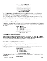
Filter 1.78 us
3
Filter 14.22 us
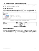
Table 8: PWM Debounce Filter
The
Number of Pulses per Revolution
parameter, if greater than 0, will convert a frequency input
into RPM instead of Hertz, based on the value entered.
1.3.8. Universal Input Data Filter
All analog inputs (Voltage or Current) can be further filtered once the raw data has been measured.
The
Data Filter
Type
parameter determines what kind of filter is used per Table 9. By default,
additional software filtering is disabled.
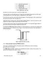
Value Meaning
0
No Filter
1
Moving Average
2
Repeating Average
Table 9: Data Filter Type
The
Data Filter Constant
is used with all types of filters as per the formulas below:
Calculation with no filter:
Value = Input
The data is simply a ‘snapshot’ of the latest value measured by the ADC or timer.
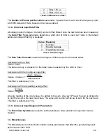
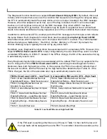
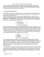
Calculation with the moving average filter:
Value
N
= Value
N-1
+
This filter is called every 1ms
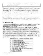
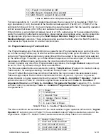
Calculation with the repeating average filter:
Value =
At every reading of the input value, it is added to the sum. At every N
th
read, the sum is divided by
N, and the result is the new input value. The value and counter will be set to zero for the next read.
This filter is called every 1ms.
1.3.9. Universal Input Diagnostic Parameters
The
Error Clear Hysteresis
is used to set the hysteresis value at which an input error can be
cleared.
1.4. Miscellaneous
The Miscellaneous function block contains various parameters that affect the general diagnostic
performance of the ECU.
(Input
– Value
N-1
)
FilterConstant
Input
N
N


