


UMAX030440 Version 2B 22-51
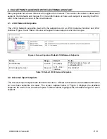
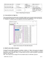
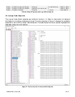
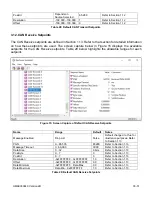
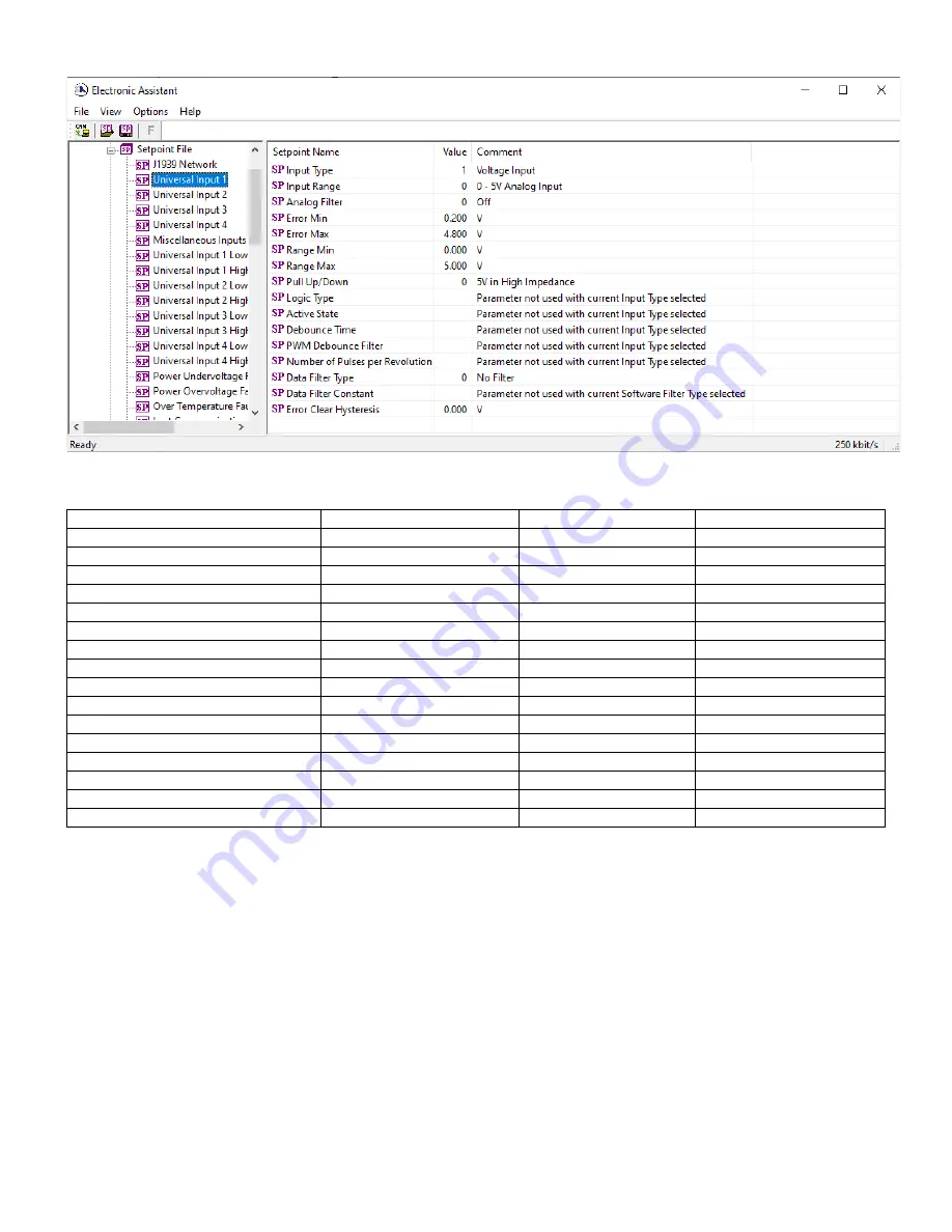
Figure 5: Screen Capture of Default Universal Input Setpoints
Name
Range
Default
Notes
Input Type
Drop List
Disabled
Refer to Section 1.3
Input Range
Drop List
0 (0-5V, or 0-20mA)
Refer to Section 1.3
Analog Filter
Drop List
Off
Refer to Section 1.3
Error Min
Depends on Input Type
Refer to Section 1.3
Error Max
Depends on Input Type
Refer to Section 1.3
Range Min
Depends on Input Type
Refer to Section 1.3
Range Max
Depends on Input Type
Refer to Section 1.3
Pull Up/Down
Drop List
No Pull
Refer to Section 1.3
Logic Type
Drop List
Input Not Implemented
Refer to Section 1.3
Active State
Drop List
Active High
Refer to Section 1.3
Debounce Time
0…65,000
10ms
Refer to Section 1.3
PWM Debounce Filter
Drop List
Off
Refer to Section 1.3
Number of Pulses per Revolution
0…1000
0
Refer to Section 1.3
Data Filter Type
Drop List
No Filter
Refer to Section 1.3
Data Filter Constant
1…1000
10
Refer to Section 1.3
Error Clear Hysteresis
Depends on Input Type
0
Refer to Section 1.3
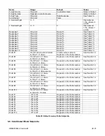
Table 20: Default Universal Input Setpoints
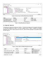
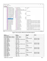
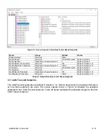
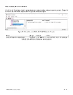
3.3. Miscellaneous Setpoints
The Miscellaneous setpoints are defined in Section 1.4. Refer to that section for detailed information
on how these setpoints are used. The screen capture below in Figure 6 displays the available
setpoints. Table 21 highlights the allowable ranges for each setpoint.


